Some of Tabor’s AWGs offer a special Digital option, which enables generating digital patterns from the rear panel of the instrument, while generating analog waveforms from the analog channels. ArbConnection offers a special Digital Pattern Composer for programming these digital bits. In this tutorial you will learn about the Digital Pattern Composer and its capabilities.
The Digital Pattern Composer is an excellent tool for creating and editing digital patterns. Each bit can be designed separately by typing in the data, or it can be filled in using special editing tools. Depending on the instrument model the digital outputs are generated from either a single or two 16 bit digital ports. If amplitude and delay control are required for these digital bits, Tabor Electronics offers a digital POD that enables control over amplitude and skew between bits.
Note
The WX series offers 32 bits digital option which is coupled with the WXD1 digital pod with its 14 channels outputs. The WW2571/2A and the PM8571/2A offer 16 bits and are coupled with the DG2816 and its 16 channels. For the purpose of this tutorial the WX2184C and its 32 bit digital outputs are used.
Once you have opened ArbConnection, to launch the Marker Composer simply point and click on the Marker tab in the Panels bar under the Composers group.
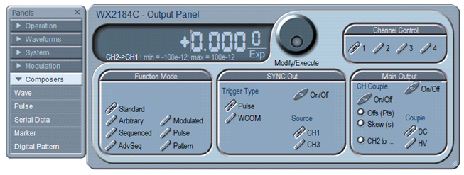
Figure 1 - Launching The Digital Pattern Composer
The Pattern Composer has three main sections:
- Pattern composer screen.
- Menu Bar.
- Toolbar.
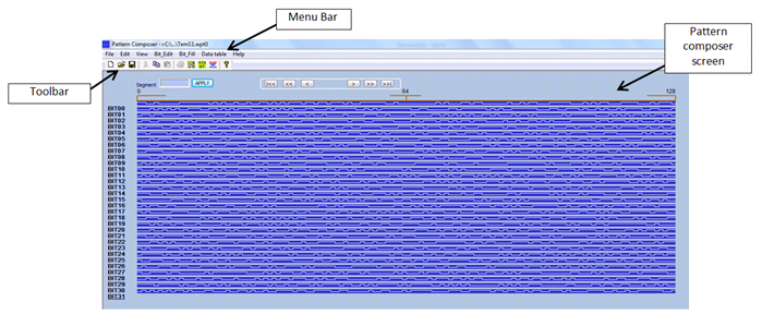
Figure 2 -The Pattern Composer
1. The Pattern Composer Screen
Waveforms are created and edited on the waveform screen as shown in figure 1. The waveform screen is divided to 32 Bits and as a default the bits are named Bit00 through Bit31. The Horizontal axis is the point number, with a numbered index at the start, middle and end of the waveform. At the top left corner is the segment number, this allows the user to change the segment to which the waveform will be downloaded to. There are various editing options that are available directly from the screen itself
• Click on the Bit Name to open a dialog box for editing the bit value.The number of points that can be edited corresponds to the View Span setting.
• Each bit value can also be changed by simply clicking on the actual waveform. A high level is changed to a low level and vice versa.
- To scroll along the segment
• There are three buttons at the top of the waveform screen
 Shifts the waveform by the small delta step size.
 Shifts the waveform by the large delta step size.
 Jumps to the start or end of the waveform.
2. The Menu Bar
2.1 File Menu
- New - Clear all and start new pattern design.
- Open… - Lets you open a saved pattern file. File extension that can be read to the composer is *.wav
- Save - If you are working on a file that you already created, you may save your progress.
- Save As… - Save your progress as a new file with a *.wav ending.
- Exit - Exit the Digital Pattern Composer.
2.2 Edit Menu
The Edit Commands are used for copying and pasting different bits. Click on the Copy command under the edit menu to open a dialog box that allows you to choose the bit to be copied and where to paste it.
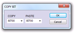
Figure 3 - Copy command
2.3 View Menu
- Span - The Span command is used for defining the number of bits displayed on screen. The user can select from predefined intervals, the max interval or a custom interval.
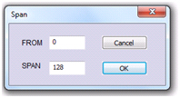
Figure 4 - The Span Command Dialog Box
- Step Size - The Step Size command defines the number of bits the pattern shifts upon clicking on the shift buttons at the top of the Pattern Composer screen. Clicking on the Step Size command invokes a dialog box where the small and large deltas are set. The Small delta is the button with the single arrow and the large delta is the button with the double arrow. Clicking on the button with the double arrow and the line shifts the pattern to the first or last bit.
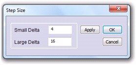
Figure 5 - Step Size Command Dialog Box
- Bit Name - The Bit Name allows for naming the different bits as they might be referred to by the user. Simply click on the Bit Name command and a dialog box will appear. Choose the bit you wish to name and type in the desired name, click on OK to confirm.
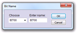
Figure 6 - Bit Name Command Dialog Box
- Toolbar - Clicking on the toolbar command toggles on and off the toolbar shown below the Menu Bar.
- Status Bar - Clicking on the Status Bar toggles on and off the status bar at the bottom of the Digital Pattern Composer screen.
2.4 Bit Edit Menu
- Math - The Math command enables the user to define a bit as the result of a logical function between two other bits. The user chooses the logical operator, the two bits to perform the operation on, and the bit where the result will be outputted. The available logical functions are: AND, OR, NAND, XOR and NOR. Clicking on the Apply button performs the operation without closing the dialog box so that the user can perform the next operation. Clicking on OK performs the operation and closes the dialog box. The Cancel button cancels the operation and closes the dialog box.
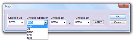
Figure 7 - Math Command Dialog Box
- Preset - The Preset command is used to easily design each bit with one of the predefined operators. These operators are: All ‘1’, All ‘0’, Invert, Shift right and Shift left. The user selects the bit, the operator, the start point where the created waveform will start and the end point where it will end. Clicking on the Apply button performs the operation without closing the dialog box so that the user can perform the next operation. Clicking on OK performs the operation and closes the dialog box. The Cancel button cancels the operation and closes the dialog box.
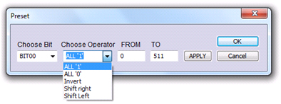
Figure 8 - Preset Command Dialog Box
2.5 Bit Fill Commands
- Random - The Random command generates random bits within the range provided by the user.
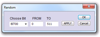
Figure 9 - Random Command Dialog Box
- Clock - The Clock command generates a Clock waveform within the range provided by the user. The user can choose the step size of the High and low levels of the clock.
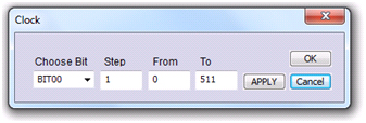
Figure 10 - Clock Command Dialog Box
2.6 Data Table Commands
The Data Table Command invokes a dialog box with a table representation of the digital pattern, and five parameters. The table consists of a point column and its corresponding value. Clicking on the Value column header opens a dialog box that allows the user to select the format of the displayed value. The options are: Hex, Decimal, Octal and Binary representation. Clicking on the value itself allows the user to edit the value of the selected point.
The digital bits are sourced from two memory options:
- Arbitrary memory - The same memory that drives the arbitrary waveform.
- Digital memory - Separate and dedicated memory that drive the digital bits only.
Due to the fact that the digital pattern is clocked at half the rate of the same arbitrary memory clock, when you assign a certain size to a segment, the number of patterns that you may load to this segment is only half of the assigned number. For example, if you assign a segment of 1024 data point, the number of patterns that can be loaded in this specific segment is 512.
The parameters displayed are:
- Digital Size - Sets the size of the current segment.
- Arbitrary Size – Lets you see the max arbitrary
- Reference 1, 2 - Reference 1 and Reference 2 are special markers used for measuring the time interval between two points.
- Delta - The time interval between the two reference markers.
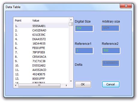
Figure 11 - Data Table
3. The Toolbar
The Toolbar contains icons for editing the waveform screen and icons for saving and loading waveforms. The Toolbar is shown in Figure 11. For the individual icons, refer to the descriptions above of the Digital Pattern Composer Menus.
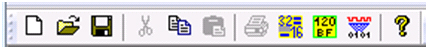
Figure 12 - The Pattern Composer Toolbar
For More Information
For more of Tabor’s solutions or to schedule a demo, please contact your local Tabor representative or email your request to [email protected].