Tabor’s ArbConnection software allows you to control all of Tabor’s AWGs via a remote PC. It is a powerful, Windows-based waveform generation software that not only allows on-screen creation and editing of waveforms, but also provides the means to access all instrument functions and features, and exploit the product’s full potential.
In this Quick start guide you will get acquainted with ArbConnection and its capabilities and learn how to work with the program. This guide will give a brief description on the functionality of each control panel and function group in it. The guide uses the WX2184C for example purposes, please note that the panels and features can differ between instrument models. For a more detailed explanation on each function/feature please refer to the instrument user manual.
Double-click on the ArbConnection icon on the PC desktop to execute the software. The startup and communications options panel will pop up. Choose your interface and startup option as explained in the connectivity tutorials and click connect. The ArbConnection software main window will open as shown below.
Note
For more information on how to install/connect the ArbConnection software to Tabor units via GPIB/LAN/USB please review the connectivity tutorials on our website.
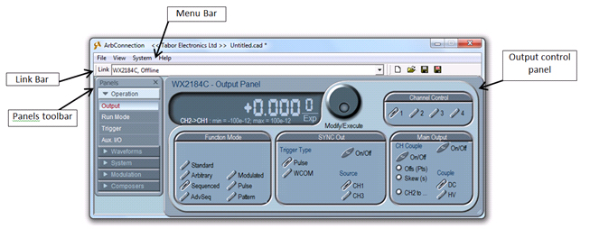
Figure 1 - ArbConnection's main window
1. Windows Menu bar
The standard Windows Menu Bar is the top bar. It provides access to main system controls like saving files, restoring previous setups and closing the program.
1.1 File Menu
- New– Use the New settings command to start a new customized settings file for the ArbConnection.
- Open– Use this command to restore previously saved settings file for your personal ArbConnection usage.
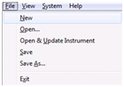
Figure 2 - File Commands
- Open & Update Instrument – Use this command to restore previously saved settings and download the required test configuration to the instrument registers.
- Save - The Save command will store your active settings as a file with a *.cad extension (Device state image file).
- Save as - will let you select name, location and format for your settings file.
- Exit - The Exit command ends the current ArbConnection session.
1.2 View Menu
- Arrange Panels - use the Cascade, Auto Cascade, Tile, Auto Tile commands to personalize the appearance arrangement of the panels.
- Log File – The ArbConnection commands are logged automatically in a log file, enabling programmers to validate remote interface programming by sending commands to the instrument from the virtual panels and then evaluating the way the commands are executed. The commands can be saved as a text file and used in external applications, exactly as ArbConnection used them.
- Options… – This command allows you to adjust and set your preferences regarding Warnings & Enables, info tips, panels sizing and common options.
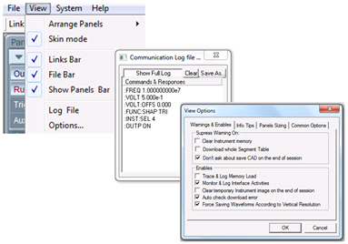
Figure 3 - View Commands
1.3 System Menu
- Startup & Communication Options – This command opens up the Startup & Communication Options dialog box.
- Command Editor – The ArbConnection also includes an editor for SCPI remote control commands. Using this, ArbConnection can be used as a controller for testing sequences of SCPI commands, which can then be used in applications such as ATE. Validate or test various commands using the Command Editor, to assure that commands or syntax used in your application will respond exactly the same way as it responds to the editor commands.
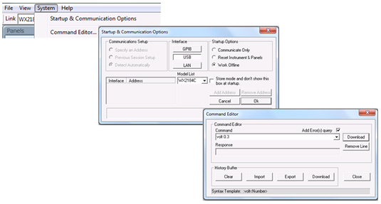
Figure 4 - System Commands
2. Link Bar
The bar under the windows menu bar at the top, is called Link bar.
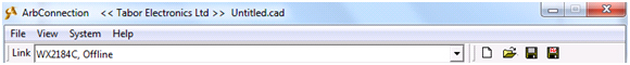
Figure 5 - Link Bar
ArbConnection can control a number of waveform generator units simultaneously. If the instruments were connected to the interface while invoking ArbConnection, they will automatically be detected by the program and will be placed in the link pull-down window.
3. The Panels toolbar
The Panels toolbar provides direct access to instrument control panels. Using the virtual control panels, you can easily access all functions and features that control the instrument. These panels look and feel like real instruments, except functions and modes are grouped into logical panels that control specific modes of operations to simplify the operation.
The digital readout on the panels has an auto-detect mechanism for the maximum and minimum limits for each of your selections. You cannot exceed the limits if you are using the dial, but only if you use the keypad. In case you go beyond the limits, the program will not let you download an illegal parameter.
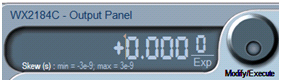
Figure 6 - Digital Readout
3.1 The Operation Panels
The Operation tab provides access to a group of panels that control the basic operation of the generator. From this group you can set the output function, run mode, turn the outputs on and off and adjust the parameters for the various functions. There are four panels in this group: Output, Run Mode, Trigger and Aux I/O. The Output panel is always visible because it is the panel that controls run modes and sets the outputs on and off. The other panels can be made visible by clicking on the appropriate tab in the Panels toolbar.
3.1.1 The Output Panel
The Output Panel, as shown below, is the first panel you see after invoking ArbConnection. If you are properly connected to a PC and ArbConnection has detected your instrument, then every time you press a button, you are getting an immediate action on the waveform generator. It is different if you are changing parameters on the display. Doing so, you’ll have to press the “Execute” or Enter button for the command to update the instrument.
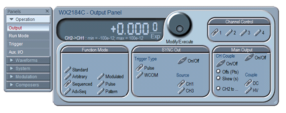
Figure 7 – Operations Tab and Output Panel
Function Mode
The Function Mode group is used for selecting between function types. The WX2184C waveform generator provides seven types of waveforms: Standard, Arbitrary, Sequenced, Advance Sequenced, Modulated, Digital Pulse and Pattern.
Sync Out
The Sync Out group is used for selecting the source, and trigger type mode.
Main Output
The Output Control group controls the on/off state of each output and channel coupling.
Channel Control
The Channel Control group has four channel buttons that determine which of the channels is currently active. Only the active channel will be sensitive to changes.
3.1.2 Run Mode Panel
The Run Mode panel selects the run mode of the instrument, allows for setting the Enable Control when in Continuous run mode and the Event In input parameters.
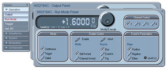
Figure 8 - Run Mode Panel
Mode
The Run Mode allows selection between continuous, triggered and gated modes.
Enable control
Select the source and mode of the Enable Control signal.
Event In Parameters
Select the triggering slope edge and sensitivity level for the Event input connector.
3.1.3 Trigger Panel
The Trigger Panel, as shown below, is accessible after clicking the Trigger button in the Panels bar. This panel controls the trigger parameters, trigger control, and smart trigger.
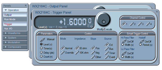
Figure 9 - The trigger panel
Trigger Parameters
The trigger parameters set the level of a valid trigger signal, the time between each trigger when using an internal trigger, delay in points between trigger signal and generated segment and a count of the number of generated segments.
Control
In the control group it is possible to select between trigger modes, trigger input impedance of the unit, trigger slope and trigger source.
Smart trigger control
This group allows you to enhance the trigger capability and facilitate wider flexibility of a specific pulse event. It allows triggering on either a pulse having a larger/smaller pulse width than a programmed time value, or even on a pulse having a pulse width between two limits. In addition the smart trigger has a hold-off function, in which the output is held idle after the first trigger and starts a waveform cycle only with the first valid trigger after a hold-off interval has lapsed.
3.1.4 Aux. I/O Panel
The Aux. I/O Panel allows you to control markers, 32 bit programmable digital outputs (when digital option is installed) and segments settings.
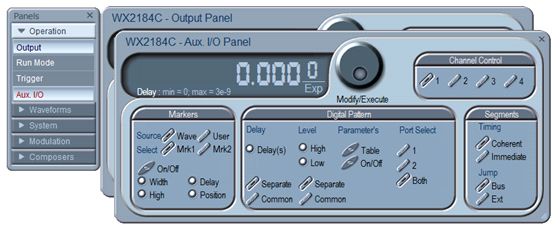
Figure 10 - Aux. I/O Panel
Markers
Markers are generated differentially through rear panel SMB connectors. This group allows you to control the settings of two differential markers for each pair of channels. In the markers group you can control the width, high level, the delay and position of the marker.
Digital Pattern
In the digital pattern group, you can control the settings of the generated digital pattern from the two digital ports on the rear panel of the generator. This group allows you to control the delay, the high and low levels, digital port selection (1 or 2 or both) and to open the Pattern Delay & Voltage Control table as seen below:
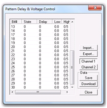
Figure 11 - Pattern Delay & Voltage Control Table
Segments
The segments group allows you to control the timing between segments: Coherent for finishing last segment before jumping to the next, and immediate to jump to the next segment immediately when a jump event (Bus or External) occurs.
3.2 The Waveforms Panel
The Waveforms tab provides access to a group of panels that control the method the signals are generated from the generator. There are four panels in this group: Standard, Arbitrary/Sequence, Digital pulse and Pattern. These panels can be made visible by clicking on the appropriate tab in the Waveforms group. The Waveforms set of panels is described below.
3.2.1 Standard Waveforms Panel
The Standard Panel, as shown below, is accessible after you click on the Standard button in the Waveforms Panels bar. The Standard Waveform Panel groups allow adjustment of channel control, parameters, and waveforms.
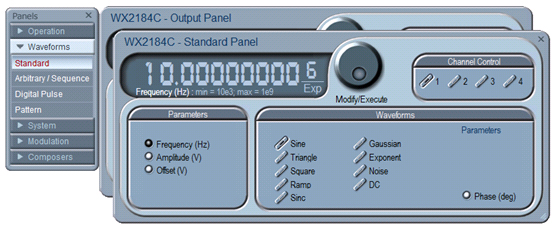
Figure 12 - Standard Panel
Parameters
The parameters group allows the user to control the Frequency (Hz), Amplitude (V), and Offset (V) of the generated signal.
Waveforms
The waveforms group allows the user to change the shape of the generated signal. You may choose between: Sine, Triangle, Square, Ramp, Sinc, Gaussian, Exponent, Noise and DC Waveforms.
3.2.2 The Arbitrary/Sequence Panel
The Arbitrary & Sequence panel, as shown below, is invoked by pressing the Arbitrary/Sequence button on the Panels bar. Note that if you invoke the Arbitrary & Sequence Panel from the Panels menu, the waveform generator will not change its output type. On the other hand, if you select the arbitrary, or the sequenced options from the Main output Panel, the waveform generator will immediately change its output to the selected waveform type. The functional groups in the Arbitrary Waveforms Panel are described below.
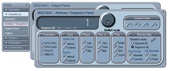
Figure 13 - Arbitrary / Sequence Panel
Parameters
The SCLK (Sample Clock) provides access to programming the value of the sample clock frequency. The sample clock setting affects the waveform generator in arbitrary mode only. It is programmed in units of S/s (samples per second). Once loops are for Once are relevant only in the appropriate sequence advance mode.
Clock
This group enables switching between External and Internal SCLK or 10MHz reference sources. By Default, both SCLK and 10MHz reference are set to internal.
Sequence/Advanced Sequence
This group provides control over advance modes for the Sequence/Advanced Sequence Generator. Advance options are: Auto, Once and Step. Refer to your waveform generator user manual to find out more on when and how to use these advance modes.
Download method
The Download Method group allows the user to define how the arbitrary waveform is downloaded to the unit memory (Available only on the WX 4 channel units). The output channels of the unit are arranged in pairs, meaning that each two channels share a single memory block of 32Mpoints (64Mpoints optional). The channel pair memory block is divided in such a way that the individual channel’s memory blocks (16Mpoints per channel in standard configuration) are interleaved in blocks of 16 points.
- Single - Waveform data is downloaded to the flash drive and then written to the selected channel memory.
- Duplicate - The same waveform data is downloaded to both channels of a channel pair.
- Zeroed - The waveform data is downloaded to the selected channel. A DC waveform (zeroes) is downloaded to the selected channel pair.
- Combined - In this mode the user has full control so waveform data must be arranged correctly. Waveform is downloaded to the selected channel pair. Waveform data must be arranged in accordance to memory limitations.
Refer to your waveform generator user manual to find out more on the various download methods.
Memory Management
The memory management group allows the user to open the waveform studio in order to create a custom table of sequenced segments or sequenced sequences, to control the number of segment/ sequence the generator currently output, control the download format: separate or common and the arbitrary waveform resolution: 1 or 2 points.
3.2.3 Digital Pulse Panel
The Digital Pulse panel is a great tool for creating and editing digital pulses without the need to think about sample clock, number of points and complex equations. The pulses are created on the panel, simply and efficiently, by typing in the period and levels, or by choosing the delay and width.
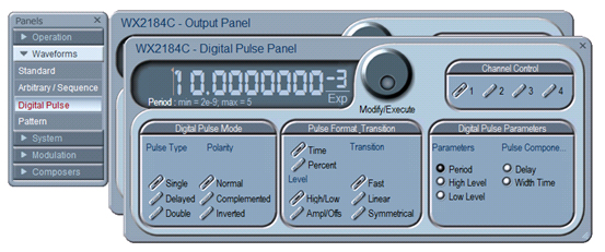
Figure 14 - Digital Pulse Panel
Digital Pulse Mode
The Digital Pulse Mode group allows the user to select between pulse types and to control the pulse polarity
Pulse Format Transition
The Pulse Format Transition group allows the user to display the pulse settings in time or percent values, control the transition method of the pulse and set the levels as high/Low or Amplitude/Offset.
Digital Pulse Parameters
This group lets the user insert the desired pulse parameters according to the configuration the user selected. Each selection the user makes in the Pulse Format Transition group reveals different configuration method to insert values to, in the Digital Pulse Parameters group.
3.2.4 Pattern Panel
Using the pattern panel allows you to generate any complex pulse train/ pattern such as single pulse, multi-level, linear-points, initialization or preamble pattern definition, user-defined or even standard random patterns with programmable resolution.
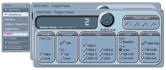
Figure 15 - The Pattern Panel
Generation
It is possible to generate two types of pulse patterns. Select pattern for generating PRBS or user defined digital patterns or Composer for creating user defined Pulse trains.
Composer
The composer allows the user to generate a pulse pattern designed by the Composer Table. There are two types of Pulse Patterns, Fast where only the level and dwell time are programmed, and linear where a start level, end level and the transition time are programmed.
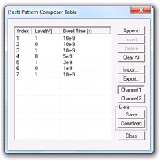
Figure 16 - Fast Pattern Composer Table
Type
In the Type group it is possible to select the pattern to be generated, either a pre-programmed PRBS pattern or a user defined pattern.
Level
The Level group enables the user to program the Baud rate and number of levels of the pattern.
Data
In the Data group the user pattern data is programmed as well as the data length, preamble and data loops. An example of a data table is shown in figure 16.
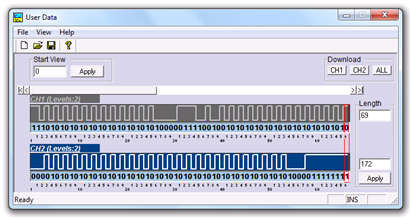
Figure 17 - Pattern Dialog Box
3.3 System Panels
The System tab provides access to a group of panels that control some general system parameters and provides access to the calibration.
3.3.1 General
The General panel provides access to some general system common commands, allows read-back of information that is stored in the instrument memory.
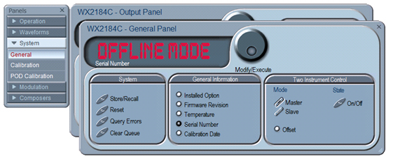
Figure 18 - The General Settings Panel
System
The System group allows for storing and recalling waveforms and setups, resetting the unit to factory default state, query errors and clearing the error queue.
General Information
In this group various system and instrument information can be found.
Two Instrument Control
When synchronizing two instruments this group defines the master and slave, turns the couple state ON or OFF and allows offsetting one instrument’s channels from the other. For more information on synchronizing two instruments go to the instrument’s user manual.
3.3.2 Calibration Panel
The Base Calibration panel provides access to remote calibration procedures. To access the remote calibration panel, you will need to have a valid User Name and Password. To qualify to perform this type of calibration, you’ll need to be trained and certified by Tabor Electronics.
3.3.3 POD Calibration Panel
The POD Calibration panel provides access to remote calibration procedures of the built in pulse generator. To access the remote calibration panel, you will need to have a valid User Name and Password.
3.3.4 The Modulation Panels
The Modulation functions were designed over four separate panels, as shown below. The panels are invoked by pressing the desired Modulation header on the panels bar. Each modulation has its own function group for setting the modulation parameters. One example of a modulation panel will be explained in detail.
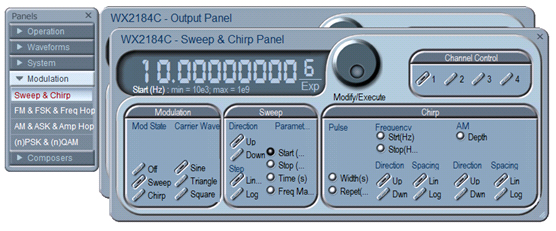
Figure 19 – Sweep & Chirp modulation Panels
3.3.5 Sweep & Chirp Modulation Panel
The Sweep & Chirp Panel enables the programming and generating of sweep and chirp modulations.
Modulation
The modulation group allows the user to select the generated modulation and the desired carrier wave shape.
Sweep
In this group the sweep modulation parameters can be set. These include: Sweep direction, step, start/stop frequencies and time.
Chirp
If a Chirp modulation is selected, one can control the AM depth, the start/stop frequency, and the pulse width and repetition.
The modulation panels provide access to all modulation functions and their respective run modes and parameters. The modulation functions that are available on these panels are:
- FM (frequency modulation).
- AM (amplitude modulation).
- Sweep.
- Chirp
- FSK (frequency shift keying).
- PSK (phase shift keying).
- ASK (amplitude shift keying).
- Amplitude and Frequency hops.
- (n)PSK.
- (n)QAM.
For detailed information regarding the available instrument specific modulations refer to the instrument’s user manual.
3.4 The Composers Panels
The Composers tab provides access to a group of composers that allow generation and editing of arbitrary waveforms, pulse shapes and pattern generation. ArbConnection offers up to five waveform composers:
Wave composer
The Wave Composer is for generating arbitrary waveforms. Arbitrary waveforms can be generated from standard libraries, from an equation editor, or imported to the composer from external utilities such as MatLAB.
Pulse composer
The Pulse Composer is for generating complex pulse trains. Unlike a standard pulse generator, you can design and edit multiple pulse trains with linear transitions and variable amplitudes.
Serial Data composer
The Serial Data Composer is for easily generating serial data patterns from the main output of the unit.
Marker composer
The Marker Composer is for easily programming the instrument’s markers.
Digital Pattern composer
The Digital Pattern Composer is for generating digital patterns using the 32bit LVDS output at the rear of the unit with a WXD1 digital pod attached.
For More Information
For more of Tabor’s solutions or to schedule a demo, please contact your local Tabor representative or email your request to [email protected].