How to Use The Pulse Editor
In this second tutorial of the series: Creating Complex Pulses and Pulse Trains, you will learn how to use the Pulse Editor and its many options. Creating pulses with the Pulse Editor is simple and intuitive, and once you draw your Pulse train, the Pulse Editor then processes the information, determines the appropriate function mode of the unit (Arbitrary or Sequence) and downloads the waveform to the instrument for generation.
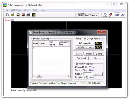 Figure 1 - The Pulse Editor Window
Pulse Editor
The Pulse Editor is the primary tool for creating pulses. To invoke the Pulse Editor, click on the Pulse Editor icon in the Pulse Composer toolbar .
.
Pulse Train
The Pulse Train is defined as the entire pulse design. When downloading the waveform to the instrument, the entire pulse train will be downloaded, even if only a part of the pulse train is displayed on the pulse composer screen.
Pulse Section
The Pulse Train is constructed from one or more sections. If the pulse is simple, it can be created using one section only. For a more complex pulse train, the train can be divided into smaller sections and each section designed separately. The figure below shows a complex pulse train, which was made from four simple sections.
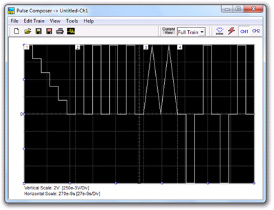 Figure 2 - A Pulse Train made up of four sections
The next figure shows the design of the fourth section only, of the full pulse train.
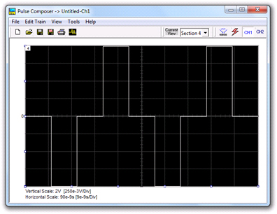 Figure 3 - Section 4 of the pulse train
Another step before you design your pulse train is to set the design parameters in the options menu that will determine the way that the pulse will be stored in your waveform memory.
1. Setting the Pulse Editor Options
As shown below, the Pulse Editor Options dialog box is divided to functional groups:
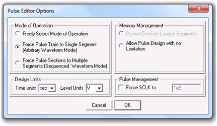 Figure 4 -The Pulse Editor Options dialog box
- Mode of Operation - There are three options in the mode of operation group. The Force Pulse Train to Single Segment option is recommended if you are using one pulse section only. In this case, the pulse waveform will occupy one segment only and the generator will automatically be set to operate in arbitrary mode. The Force Pulse Sections to Multiple Segments option will place each section of the pulse train into a different memory segment and the generator will automatically be set to operate in sequenced mode. If you are not sure what to do, select the Freely Select Mode of Operation and the generator will do the work for you.
- Design Units - As you design your pulse pattern, it will be easier if you design it using the exact units as you would want to output to your load. Select between nsec, µsec, msec and sec for the pulse intervals. Select between mV or V for the amplitude level.
- Memory Management - There are two options in the Memory Management group. The Do Not Override Loaded Segments option will make sure that whatever waveforms you already stored for the arbitrary function will stay intact after you save your pulse waveform. The Allow Pulse Design with no Limitations option may overwrite memory segments that you already used previously for the arbitrary function.
- Pulse Management – This Parameter enables you to force the instrument to use a specified sample clock. The Pulse Composer creates the designed pulse with the least amount of memory possible. Therefore the Force SCLK allows you to set the increment between points so that a higher resolution can be achieved. This option is also a must when downloading 2 different pulses to 2 channels. Without the Force SCLK each time a pulse is downloaded to a channel a new SCLK will be set changing the Pulse in the other channel (not relevant for generators with separate sample clock for each channel pair).
2. Using the Pulse Editor
To invoke the Pulse Editor, point and click on the Pulse Editor icon on the tools bar.
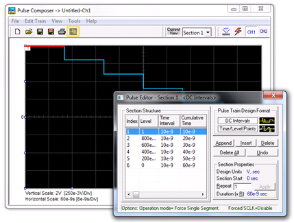 Figure 5 - Constructing a section using the pulse editor
The Pulse Editor has four groups:
1. Pulse Train Design Format.
2. Section Structure.
3. Section Properties.
4. Control buttons.
2.1 Pulse Train Design Format
The design format is unique for the current section and cannot be switched during the section design. There are two methods (or formats) that can be used for designing the pulse shape:
DC Intervals – programs pulse duration using DC levels only. Transition times for this format are at the maximum rate that the generator can produce.
Time/Level Points – programs pulse turning points using level and time markers. This format is a bit more complex to use. However, it allows pulse designs that require linear transition times.
Note
As you build the segments that the pulse is being drawn on the screen as you type in the parameters. Also note that the Cumulative Time column is updated automatically with the cumulative time lapse from the start of the pulse.
2.2 Section Structure
The term Section Structure is used to define parts of the pulse train that share common properties. There are four parameters that can be programmed in this group:
- Index – Is added automatically as you program pulse segments. The index line is highlighted as you point and click on Pulse Segments on the pulse editor screen.
- Level – Specifies that peak level of the programmed segment. As you build the pulse, the level window is automatically expanded to fit the required amplitude range. Note however, there is a limit to the level, which is determined by the generator’s peak-to-peak specification.
- Time Interval – Specifies the time that will lapse for the current index level. You can program the time interval and the cumulative time will be adjusted accordingly.
- Cumulative Time – Specifies the time that will lapse from the start of the current pulse section. You can program the cumulative time and the last time interval will be adjusted accordingly.
2.3 Section Properties
The Section Properties contain a summary of properties that are unique for the current section.
- Design Units – Provide information on the units that are used when you draw the pulse segments. These units can be changed in the Pulse Editor Options menu.
- Section Start – Provides timing information for the start of the current section. If this is the first pulse section, the value will always be 0. Subsequent sections will show the start mark equal to the end mark of the previous section.
- Repeat – Allows multiplication of pulse segments without the need to re-design repetitive parts. After you enter a repeat value, press the Apply button to lock in the repeat multiplier.
- Duration - Displays the time that will lapse from the start of the pulse section to the end. The duration shows the total time lapse, including the repeated sections.
2.4 Control Buttons
The Control Buttons allow appending, inserting, and deleting one or all index lines. The Undo button is useful in cases where an error was made and restoration of the last operation is critical.
Now that you are familiar with the Pulse Composer and Pulse Editor, for a step by step example of how to generate a pulse train please refer to the next tutorial in the series, Creating Complex Pulses and Pulse Trains Part 3 - How To Simply Design a Pulse Train.
For More Information
For more of Tabor’s solutions or to schedule a demo, please contact your local Tabor representative or email your request to [email protected].