This tutorial will show how to synchronize two Tabor WW5064/WW1074/WW2074 using Tabor remote control software - ArbConnection, in order to achieve up to 8 synchronized channels.
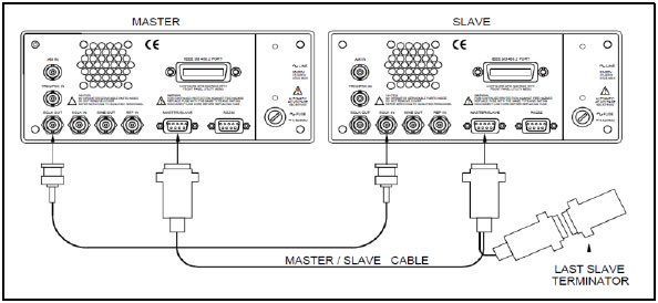
For synchronizing between two units of other models (one or two channel units requires a dedicated synchronization cable as can be seen in the picture below), this procedure is much simpler. In this case, please look for instructions how to perform synchronization in the user manual of each specific model.
1.Connect the two Instruments:
Synchronization is done by connecting both instruments to LAN communication and assigning to each AWG a TCPIP address through its front panel and by connecting the two AWG’s as can be seen in the picture below:
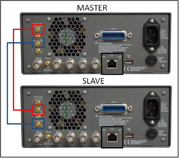
Multi-Instrument Synchronization is comprised of four SMB connectors, designated as:
- SCLK-OUT: This SMB connector outputs the programmed sample clock frequency. Output level is 400mVp-p, terminated into 50Ω. Note that correct termination is necessary for this output otherwise you will not see this signal at all. This output generates sample clock waveforms continuously, regardless if the AWG is operating in continuous, trigger, or gated modes.
The sample clock output is used for multiple-instruments synchronization. In master mode, connect this output with an SMB to SMB cable to the SCLK IN on the adjacent slave instrument. You may also use this output to synchronize other components in your system to one master clock.
- SCLK-IN: This SMB connector accepts 300mVp-p to 1Vp-p into 50Ω level signal. Normally, this input is disabled. When enabled, the clock at this input replaces the internal clock generator and the AWG generates waveforms having the external sample clock rate.
When synchronizing your AWG as a slave unit, an SMB to SMB cable is connected from the Master SCLK OUT connector to this SCLK IN connector.
- COUPLE-OUT: This SMB connector outputs the coupling signals to the slave unit. Output level is LVPECL, terminated into 50Ω to 1.3V. For multi-instrument synchronization, connect this output to the COUPLE-IN.
- COUPLE-IN: This SMB connector accepts coupling signals from the master unit. Input level is LVPECL, terminated into 50Ω to 1.3V. For multi-instrument synchronization, connect this input to the COUPLE OUT connector on the master unit.
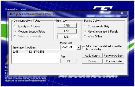
2. Connect with the MASTER unit through ArbConnection:
- Open ‘Log File’ to view the commands being sent to the AWG:
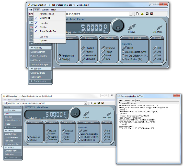
- Press the ‘X-Instrument Sync’ button on under ‘Auxiliary’. A new window will open up:
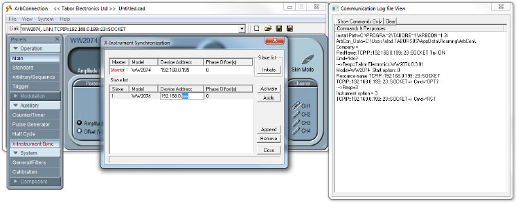
- In the SLAVE table, change the TCPIP address to the one of the SLAVE AWG (make sure the MASTER’s address is higher). Press the ‘Initiate’ button :
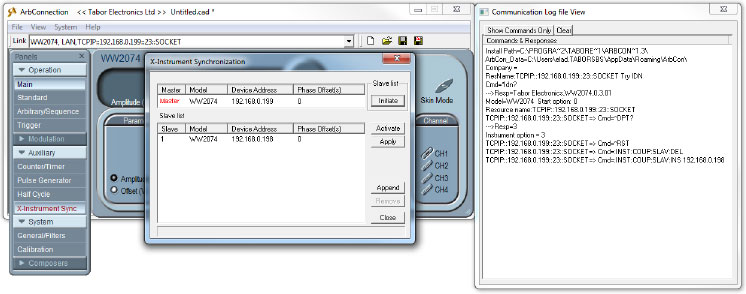
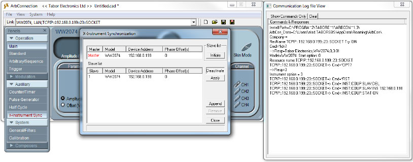
- Press the ‘Activate’ button. You can see the corresponding SCPI commands used to perform this action:
3.Control the two AWGs while in Synchronization mode:
Generally speaking, when controlling two AWGs using the MASTER-SLAVE feature:
I. Sample clock and output frequency can only be controlled from the master unit’s panels.
II. Both master and slave units must be placed in the same run mode to operate synchronously. For example, units in burst mode will synchronize however, one set to continuous and the other to burst will result in software conflict error.
III. Both master and slave units must be placed in the same function mode to operate synchronously. For example, both units in sequence mode will synchronize however, one set to Arbitrary and the other to sequence will result in software conflict error.
IV. Two instrument’s synchronization does not operate in modulated waveform mode.
V. Trigger signal is applied to the master input and is common to both master and slave units.
VI. Each instrument can have a unique set of waveforms, active segment, sequence, amplitude and offset parameters.
VII. Slave channels can be delayed in reference to the master channels by a pre-defined number of sample clocks.
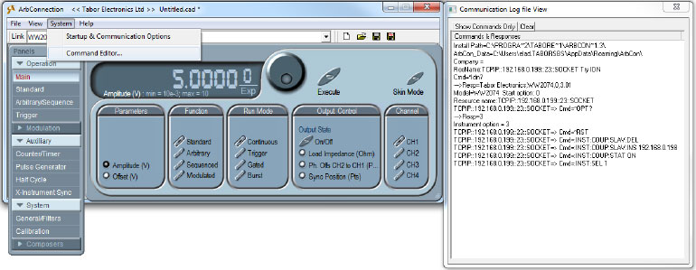
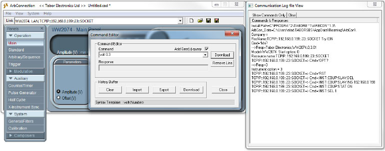
All common attributes such as function/run modes can be set by the Arbconnection MASTER’s panels, same as working with only one generator. If you would like to set different attributes to the SLAVE AWG (for example different amplitude & offset for each AWG), this is done by sending SCPI commands. In order to do so, open the Command editor (note that also the MASTER AWG can be controlled by SCPI commands):
- The Command Editor will open up. If you press the Download button, the function call in the Command field will be sent to the instrument. Low-level SCPI commands and queries can be directly sent to the WW series AWGs from the Command field and the instrument will respond to queries in the Response field. A complete list of the available SCPI commands can be found in each instrument’s user manual (Chapter 5).
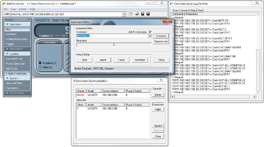
- In order to see that the outputs of the two AWG are in-synced, use SCPI commands to control the two instruments:
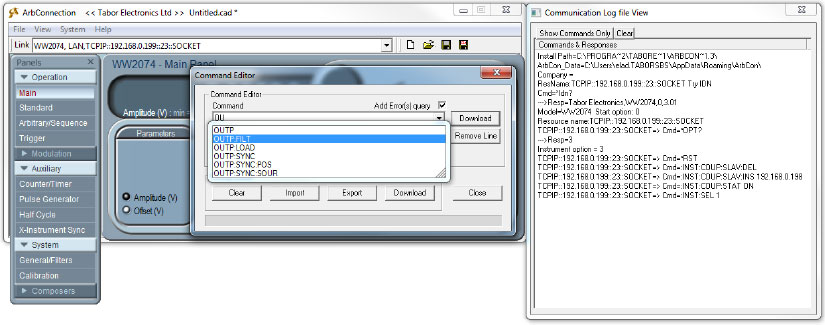
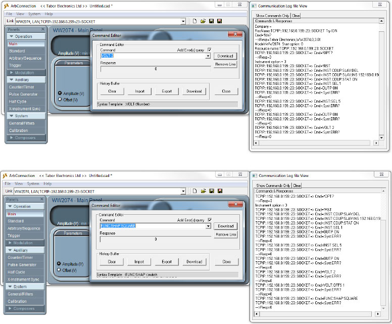
- By default, the active channel is automatically set to MASTER channel 1. Open its output using the SCPI command ‘:OUTP ON’. The Command editor will auto-complete (as can be seen above) the command you are about to write. Press enter when finished typing the correct command:

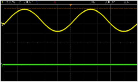
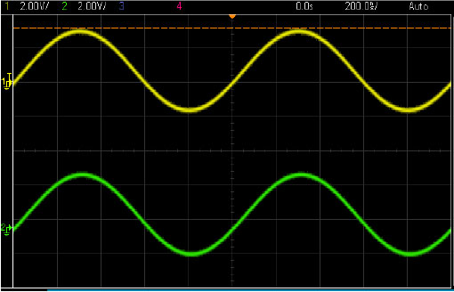
- As can be seen on scope channel 1 of MASTER AWG is on:
- When controlling through ArbConnection, the 4 channels of the SLAVE AWG are now CH5, CH6, CH7 & CH8. Select channel 5 (ch1 in SLAVE AWG) to be the active channel by typing ‘:INST:SEL 5’ and pressing Enter:
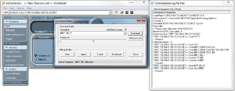
- After setting CH5 to be active, by typing ‘:OUTP ON’ you will turn CH1-SLAVE on:

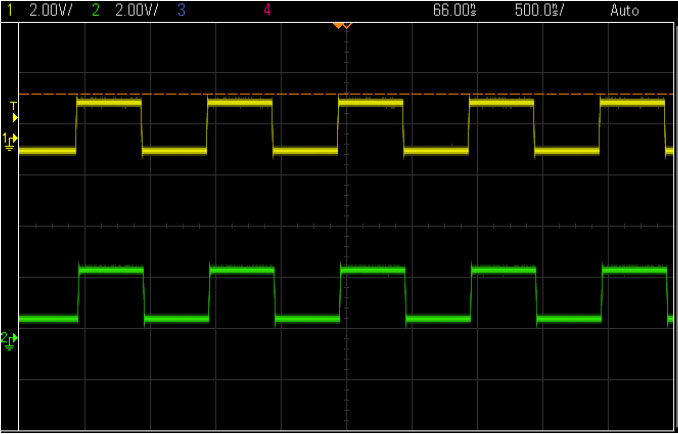
- As can be seen on Scope, you can see the two instruments are in-synced:
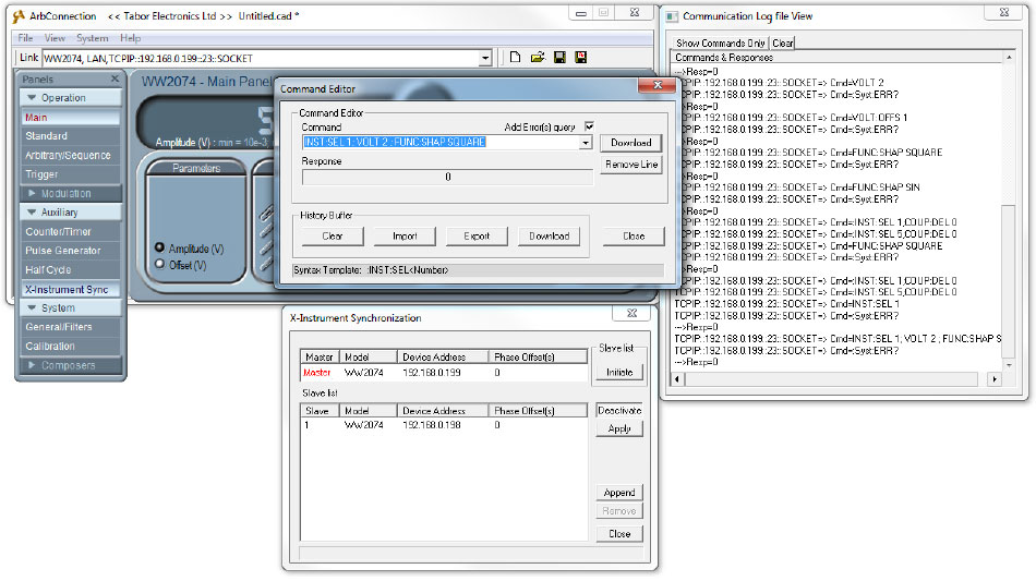
- The last call to the active channel was ‘:INST:SEL 5’ so you can set the amplitude & offset of the SLAVE’s channel 1 using the ‘:VOLT _’ & ‘:VOLT:OFFSET _’ commands. For example if you would like to change the amplitude, offset and waveform shape:
I. ‘:VOLT 2’
II. ‘:VOLT:OFFSET 1’
III. ‘:FUNC:SHAP SQUARE’
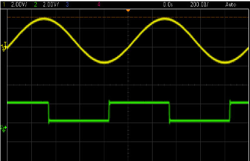
- As can be seen on scope the amplitude, offset and shape have changed accordingly:
4.Set the phase difference between the two AWGs outputs:
After changing the shape of the waveform, you could align the two AWG’s outputs by pressing the ‘Apply’ button as can be seen below:
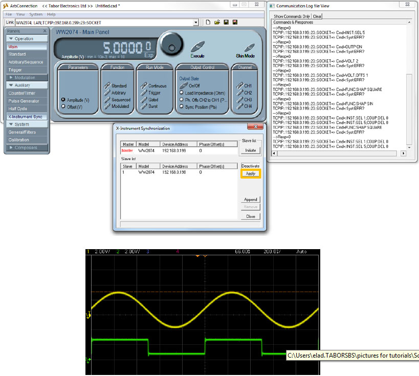
5. The next screenshots demonstrate how to control the MASTER’s channel using SCPI commands. Same operations can be done using the ArbConnection panels:
- Setting the phase difference between the two AWGs defines the delay time that one instrument will hold off before it will start generating the output waveform. Minimum resolution is 20 ns and the delay can be programmed from 200ns to 20s.
Please note that there will always be skew between adjacent instruments, which is due to circuit delays and cable length. Always consider the initial skew in your inter-instrument delay calculations. The initial waveform skew on the slave unit is roughly 25ns.
For More Information
To learn more about Tabor instruments, visit our website Support & Tutorials zone. For more of Tabor’s solutions or to schedule a demo, please contact your local Tabor representative or email your request to [email protected]. More information can be found at our website at www.taborelec.com