In the next tutorial, you will find detailed information on how to synchronize between two Tabor high speed AWGs:
- Using 10MHz/100MHz reference input feature
The External Reference input is useful for applications requiring synchronization to another AWG or to other components in a system, and can be used to improve clock stability and accuracy, but it does not necessarily improve phase noise and won’t allow you to control the skew between the synchronized AWGs. The external reference input is a BNC connector that is located on the rear panel. It sends/accepts signals within the frequency range of 10MHz, 20MHz, 50MHz, 100MHz. Note that the channels of each instruments do not have to be synchronized to use the external reference feed.
One could access the External Reference Clock parameters from the front panel’s Utility menu. When the selected parameter is highlighted, press the enter key and use the up/down buttons to select the required option. Press Enter to complete the action and to lock the selected mode.
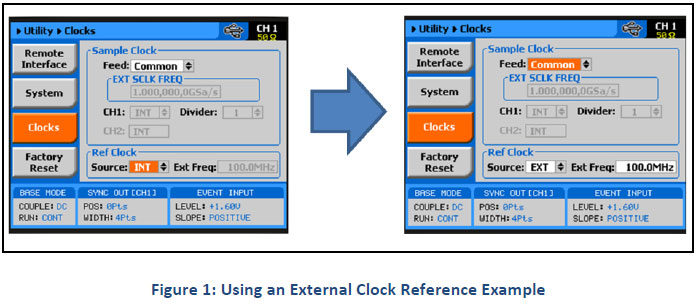
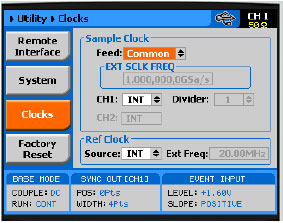
As shown in figure 1, there are two parameters that can be accessed in the Reference Clock group:
SOURCE – Use this field to select between INT (internal) or EXT (external) reference clock feeds. Note that updating the EXT FREQ field with the external frequency value is necessary for the external reference clock feed function to operate correctly.
EXT FREQ – this field becomes active only after you select an external reference feed. This field is necessary for the instrument to establish a frequency range for the internal phase lock loops and therefore it is recommended to be programmed exactly as the external reference source frequency. Figure 1 shows an example of a setup that provides external feed frequency of 100MHz.
For example:
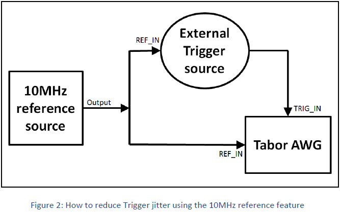
One of the uses is to synchronize between an external Trigger source to Tabor AWGs. This is done to reduce Trigger jitter.
- Using the X-instrument (MASTER-SLAVE) feature
This method gives you the option to fully synchronize between two instruments of the same model (for example two WX2182C). This synchronization technique allows you to control the skew between the two instruments with resolution of 10ps.
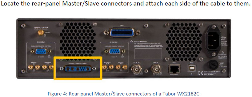
1. Connectivity
In order to fully synchronize between two Tabor AWGs, the two must be cross-connected with a special designated synchronization cable:
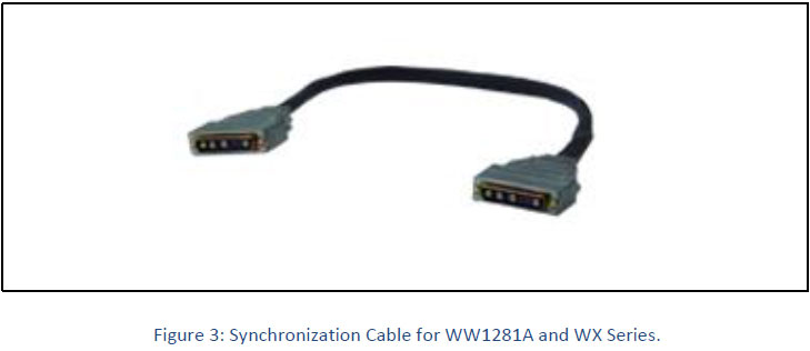
NOTE
The connectors do not lock into position without screwing-in the bolts on each side. Use a flat tip screwdriver to latch the cables into their receptacle housing, making sure the connectors are straight and firmly locked into place.
2. Reset of the instruments
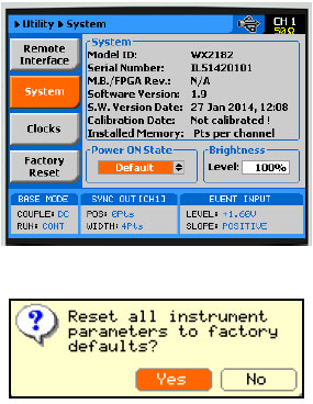
Once the two instruments have been connected to each other using the special cable, perform a factory reset in each one of the AWGs:
I. Press the “Utility” button.
II. Press the “Factory Reset” soft-key.
III. Choose “yes”.
IV. Press Enter to confirm.
3. Select the Channel Couple Mode
When synchronizing two instruments, it is possible to reach a max of 8 fully synchronized channels (4 channels with the WX2182C). If on each unit, you are setting the clock feed to be “Separate” (meaning separate sample clock for each channel, or channel pair with the 4CH WX unit), then only the active channels on each AWG will be in sync.
For example:
If in the Slave AWG, CH1 is active and in the Master AWG, CH1 is active and the clock of each channel is set to separate mode, then only those two channels will be synchronized. If on each unit, the clock feed is set to “Common” (meaning all channels will share the same sample clock feed), then all the channels will be synchronized.
Here are the steps:
I. Press the “Utility” button.
II. Press the “Clocks” soft-key.
III. Choose the “Feed” field.
IV. Using the dial or up cursor key, change the setting to “separate” to sync between two specific channels, or change to “common” in order to synchronize between all the channels.
V. Press Enter.
4. Select a Master AWG
Select one AWG as the Master and the other as Slave:
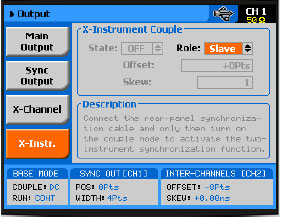
Using the ‘Slave’ AWG’s front panel:
I. Press on the “Output” button.
II. Scroll down & press the “X-Instr.” soft-key.
III. Change the “Role” option to “Slave”, press Enter.
IV. Turn on the channels outputs.
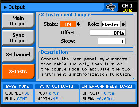
Using the ‘Master’ AWG’s front panel:
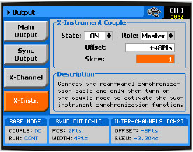
I. Press on the “Output” button.
II. Scroll down & press the “X-Instr.” soft-key.
III. Change the “Role” option to “Master”, press Enter.
IV. Change the “State” field to “ON” and press Enter to activate the “MASTER-SLAVE” mode.
V. Turn on the channel outputs.
5. Operating Two Synchronized AWGs
Here are a few things that you should be aware of, before you start operating the two synchronized AWGs as one:
I. The synchronization is activated from the Master unit only.
II. Before activation of the synchronization, both Master and Slave AWGs must:
a. Be set to the same sample clock and output frequency. After synchronization took place, the sample clock and output frequency of both AWGs could be controlled from the Master AWG only.
b. Must be set to be in the same run mode. For example, both AWGs are set to be in continuous mode and will synchronize; however, one set to continuous and the other to trigger will not synchronize.
c. Must be set to be in the same function mode. For example, both units in sequence mode will synchronize, however, one set to arbitrary and the other to sequence will not synchronize.
d. In Sequence mode, both Master and Slave units must have a sequence table with the same number of steps.
III. The trigger signal is applied to the Master input and is shared to both Master and Slave units.
IV. The Slave output can be delayed from the Master output by a predefined number of sample clocks. There are two parameters you can change:
a. “Offset” for coarse tuning.
b. “Skew” for fine tuning.
You can set an offset between the two AWGs outputs by changing the sample clock cycles, or waveform points that the instrument will hold off before it will start generating its output. When there is a need for fine tuning (a better resolution and accuracy), the skew can be varied from -3 to +3 ns at a 10-ps resolution.
I. Press the “Output” button
II. Press the “X-Instr.” soft-key.
III. Start with changing the offset. The resolution is of eight waveform points.
IV. Adjust the skew between the instruments for fine tuning.
For More Information
To learn more about Tabor instruments, visit our website Support & Tutorials zone. For more of Tabor’s solutions or to schedule a demo, please contact your local Tabor representative or email your request to [email protected]. More information can be found at our website at www.taborelec.com