In the previous tutorials, we have shown how to install all the necessary drivers and how to communicate with Tabor AWG using SCPI commands. Another way of using LabVIEW to control Tabor AWGs, is by using the Tabor IVI driver. This way, one can communicate with the Tabor AWG, using pre-defined functions. In this tutorial, we will give a quick start guide on how you can communicate with the Tabor AWG using the IVI driver.
For this tutorial, we will use LabVIEW 2015 32bit and a USB interface, together with the Tabor WX2184C and its latest version of the WX218x 32bit IVI driver. While there are differences when using other Tabor families of instruments the basics are the same. To ensure you successfully established all the necessary settings for remote control over the Tabor instrument using LAN/USB/GPIB, please go over our connectivity tutorials on Tabor’s website.
- To connect and control the Tabor’s Instrument using the IVI driver
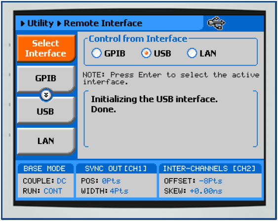
1. Set the USB/LAN/GPIB as the remote interface, using the Tabor’s front panel buttons. To do so, go to:
“Utility”->”Remote Interface”->”Select Interface”->”Control from Interface”. Press Enter to select the active Interface you need. Wait for the answer “Done”. We chose to demonstrate using USB.
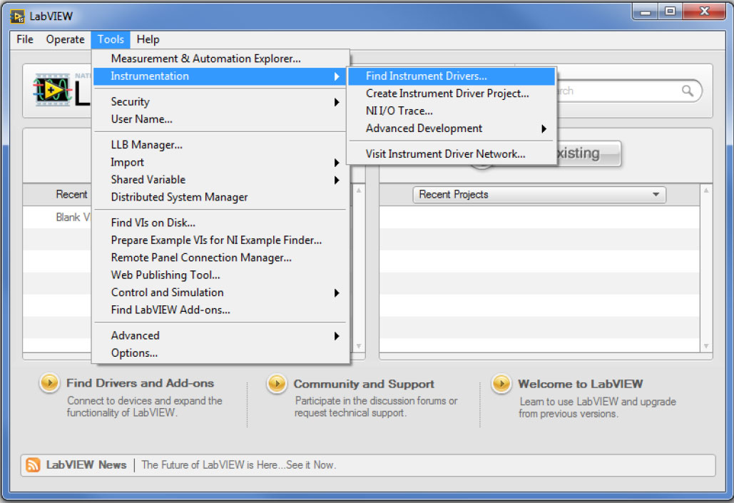
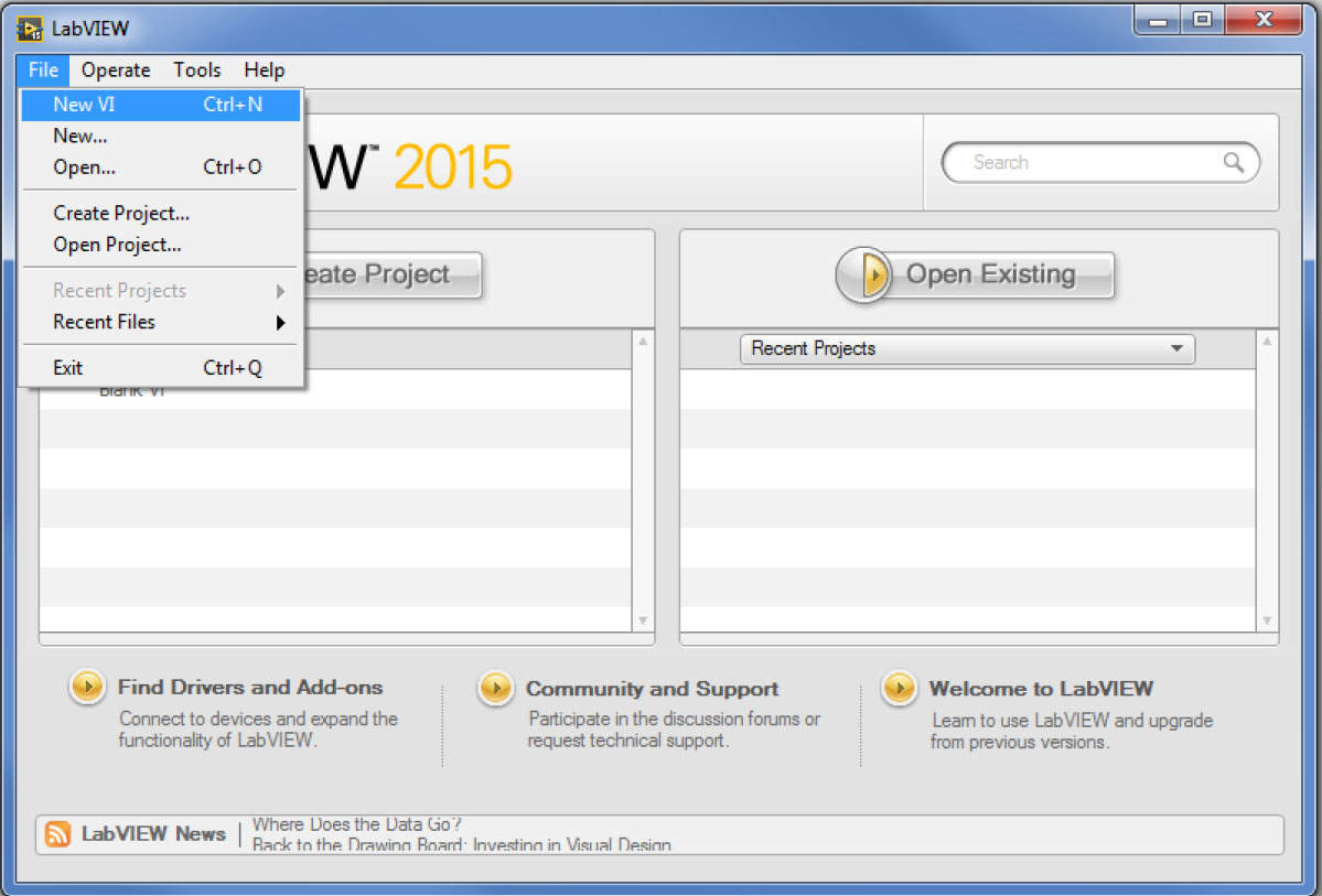
2. Once the LabVIEW is up and running, go to Tools->>Instrumentation->>Find Instrument Drivers…
Expand the installed Instrument drivers to see what drivers are installed. Expand the Connected instruments to see if LabVIEW identifies the Tabor unit.
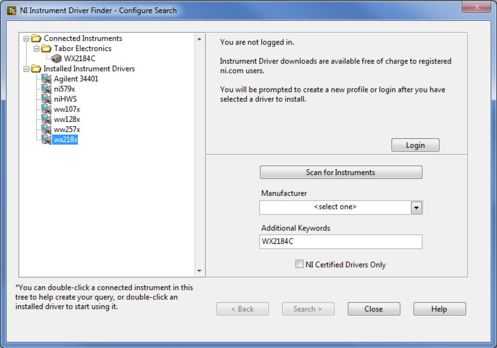
Double click on the ‘wx218x’ icon, it will open a new window.
NOTE
If the Tabor driver isn’t visible on the NI Instrument Driver Finder, please refer to the instructions in “How to Control Tabor AWGs with LabVIEW – Getting started” tutorial, regarding how to copy & paste the ‘wx218x’ folder into LabVIEW’s instr.lib folder.
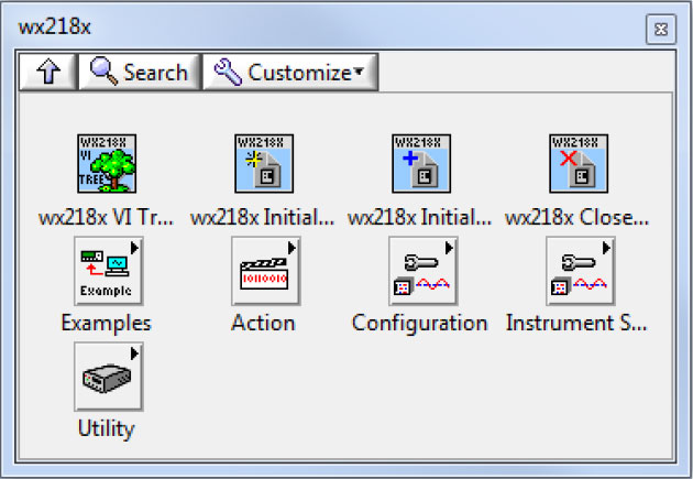
3. Click on the ‘Open Palette’:
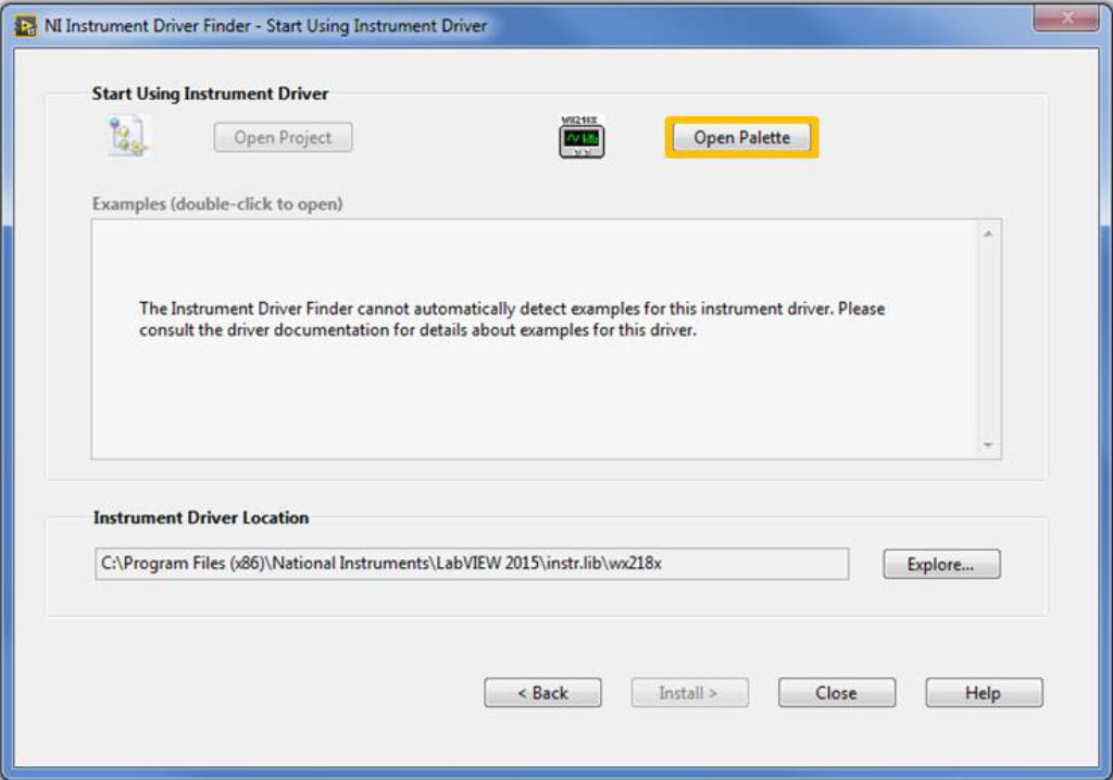
It will open the Tabor wx218x VIs Palette, which you could use to drag & drop each VI found in the IVI driver’s wrapper, to your generated code:
4. Right click on the ‘wx218x VI tree’ & choose to ‘Open VI’:
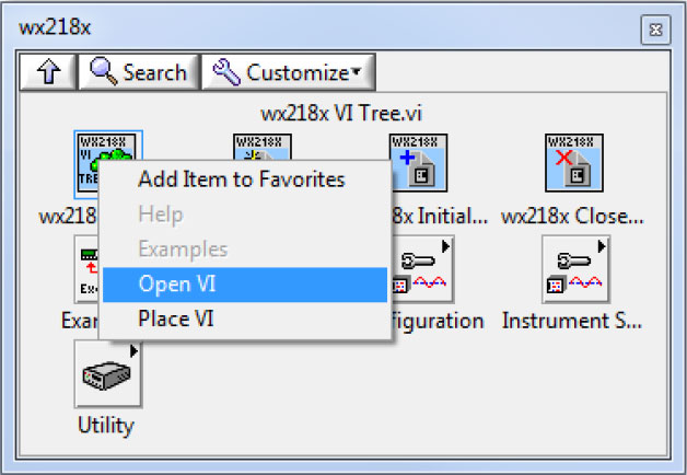
It will show you all the available VIs in the Tabor VI tree:
5. You can reach the Tabor VI tree in a similar way:
a. open a new VI:
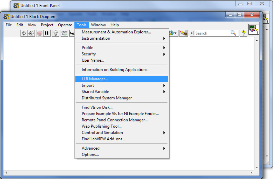
b. Go to Tools->>LLB manager…
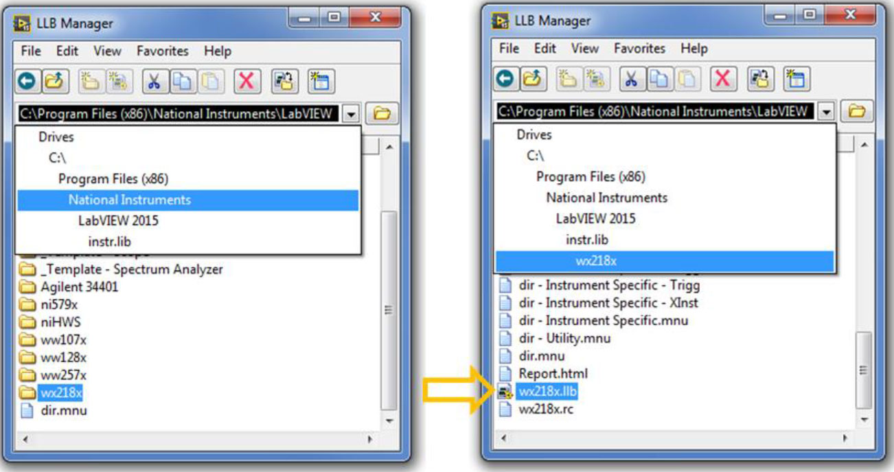
c. Select the path as seen below,then double click on the wx218x.llb file:
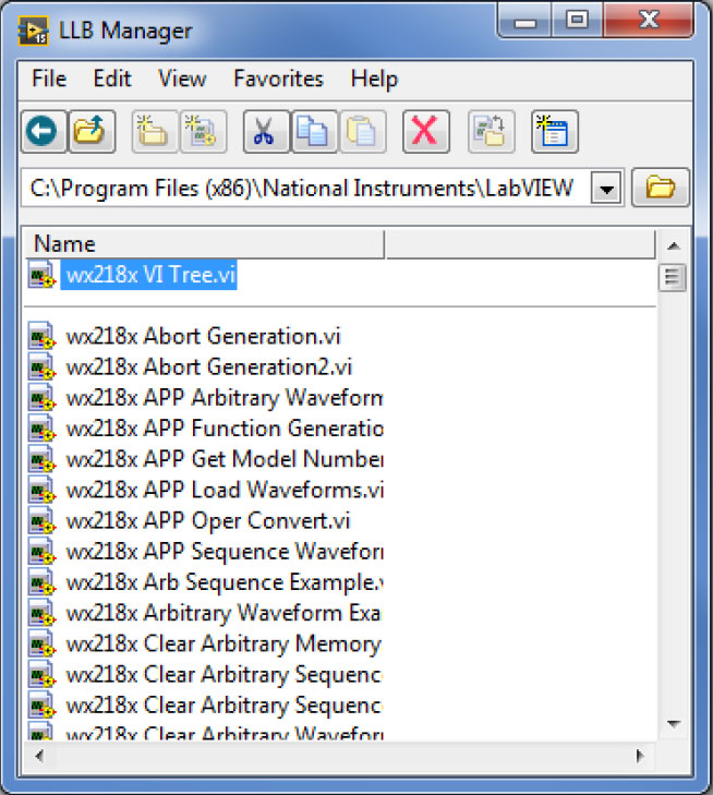
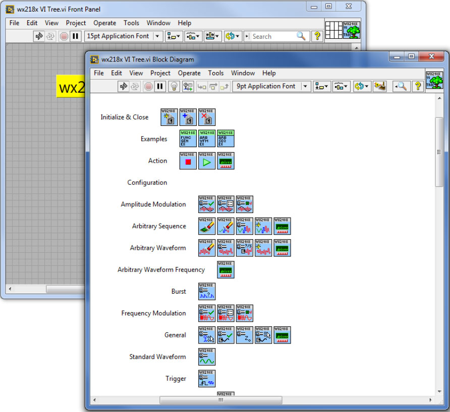
d. Double click on the ‘wx218x VI Tree.vi’:
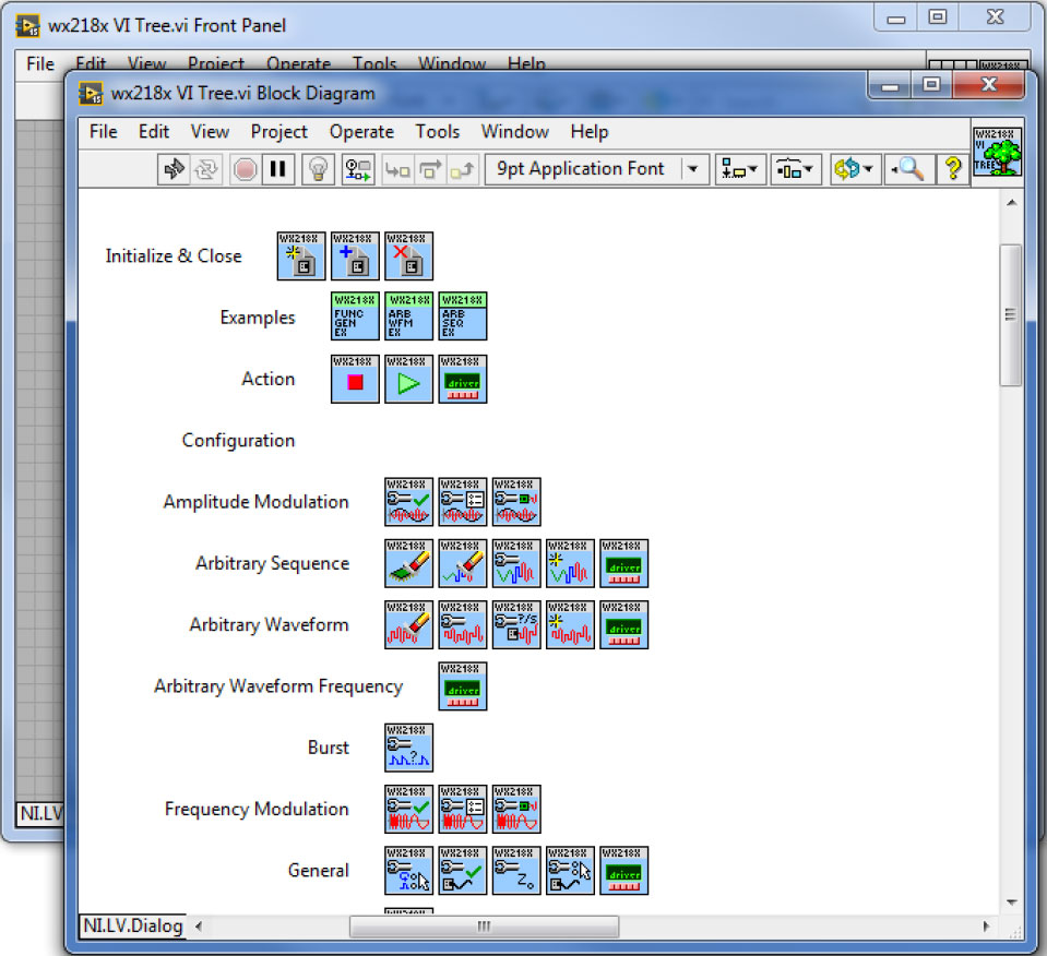
e. Once it will open, go to Window->>Show Block Diagram:
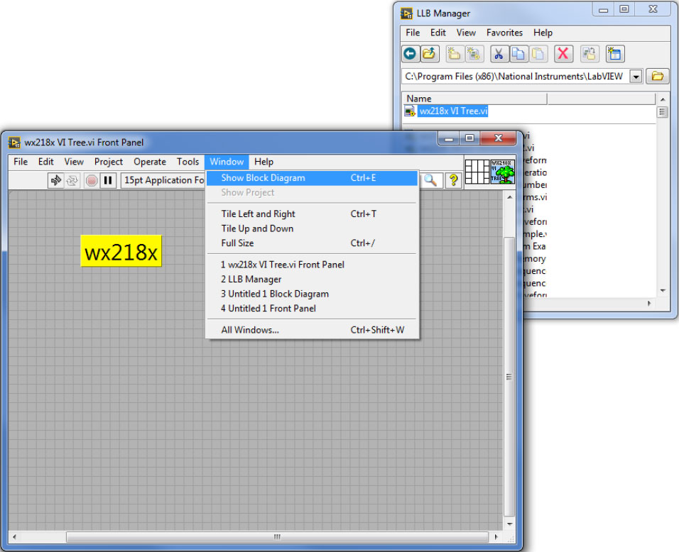
It will show you all the available VIs in the Tabor VI tree:
6. Here is a short basic example, to set a 50MHz 2Vp-p square waveform in standard mode, just to get a feel of how to communicate using the Tabor IVI driver VIs:
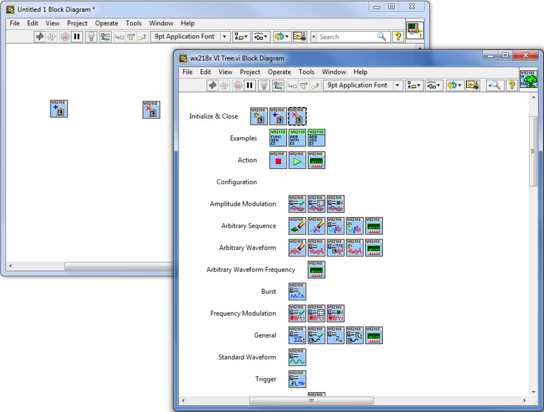
a. Drag & drop the ‘Initialize with Options.vi’ and the ‘close.vi’ to a new blank VI:
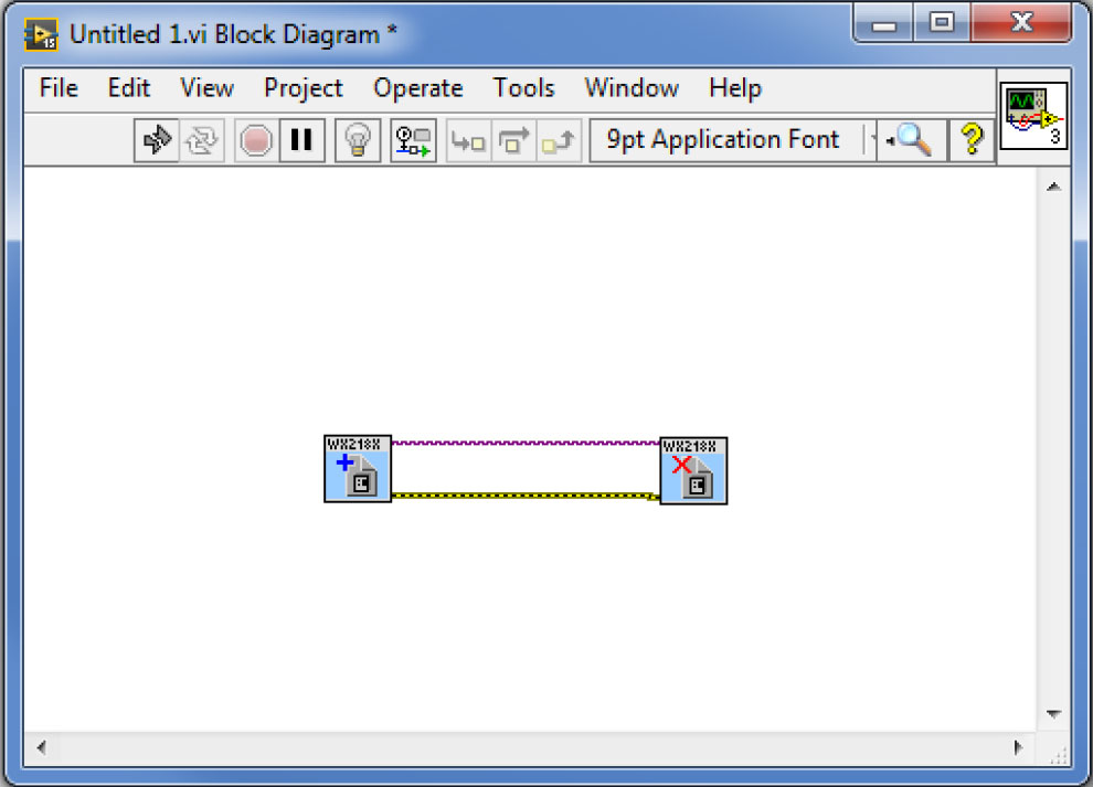
b. Wire them as seen below:
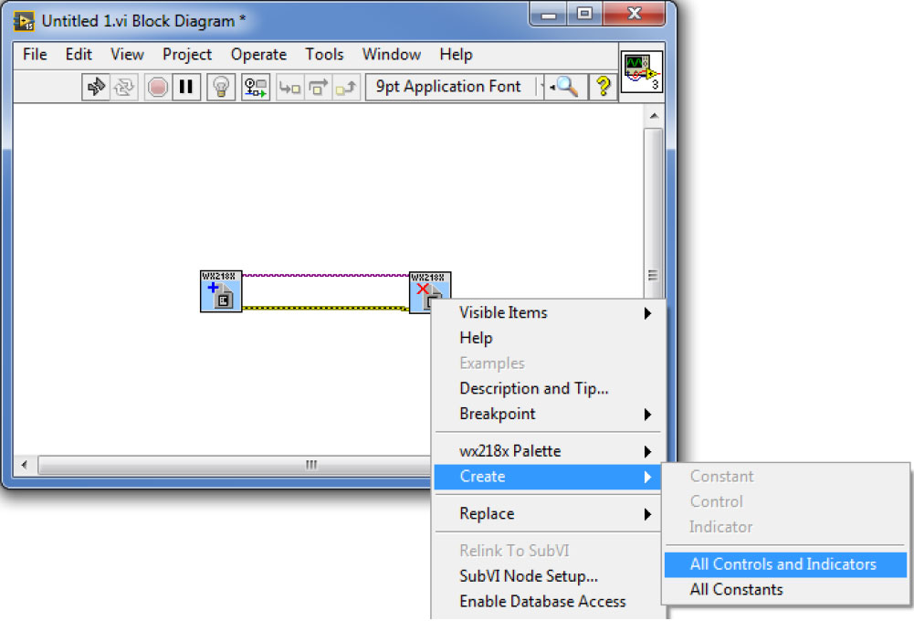
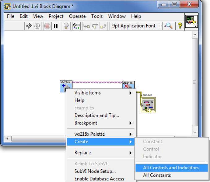
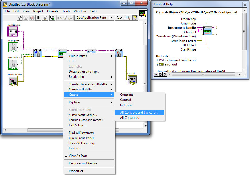
c. Create an Error-out indicator for the ‘Close.vi’ by right clicking on the VI and choosing to create all controls and indicators as can be seen below:
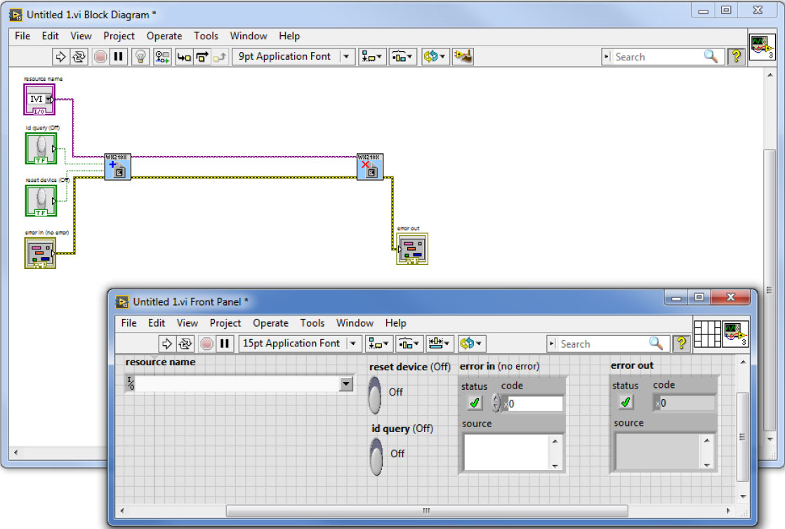
d. In the same way, create all controls and indicators for the ‘Initialize with options.vi’:
e. Delete the Optional string control, as it is not necessary at this point:
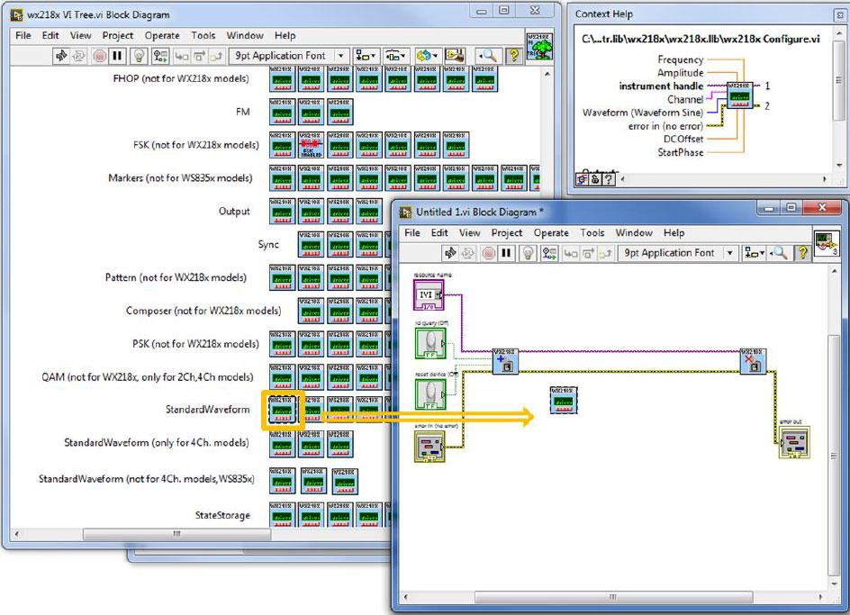
f. Drag and drop the ‘wx218x Configure.vi’ found under Standard Waveform:
g. Do the same for the ‘wx218x Configure Output Enabled.vi’:
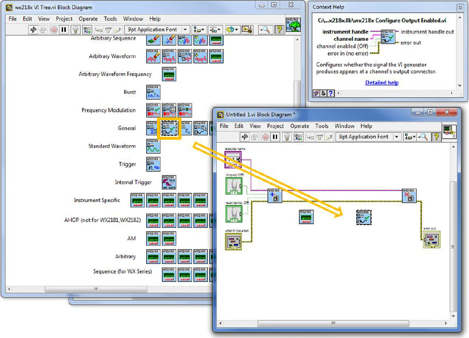
h. Wire them as with the initialize & close VIs in a row (handle and error wires). Right click on the ‘wx218x Configure.vi’ to create all controls and indicators:
i. Do the same for the ‘wx218x Configure Output Enabled.vi’. Make sure you wire the VIs as can be seen below:
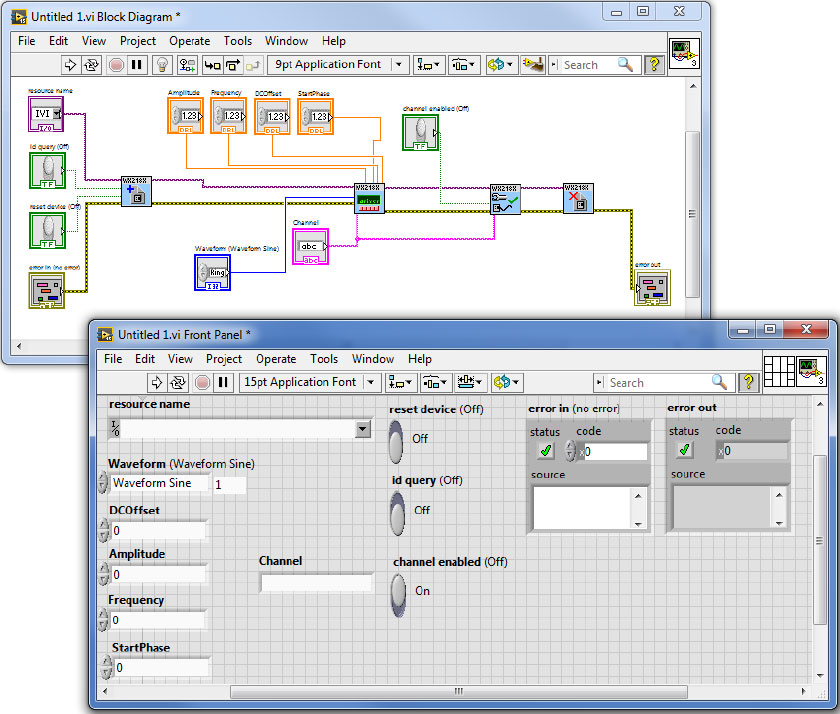
j. Now that we are all set, please go to the VI’s front panel and choose the Tabor’s resource name. Set to ‘Waveform Square’, offset 0V, Amplitude 2Vp-p, Frequency 50MHz. Choose the active channel to be ‘Channel1’ and set the ‘channel enabled’ to ‘On’ as can be seen below:
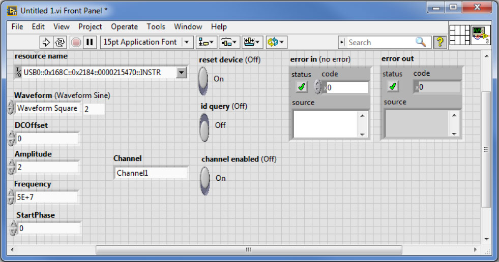
Press the run button.
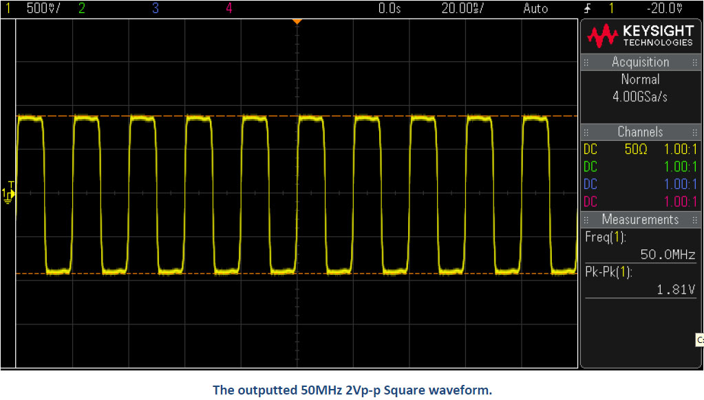
7. As can be seen on scope, a 50MHz 2Vp-p square waveform was created:
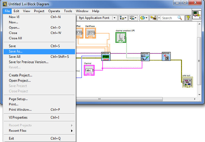
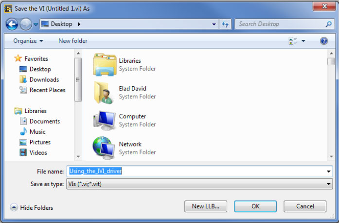
8. In order to save this process as LabVIEW code, go to File->>Save as…
9. Go to the ‘wx218x VI Tree’ block diagram and double click on the ‘Function generator Example’ VI:
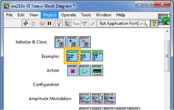
This example shows how to use standard mode. It also shows how you can change some of the parameters on the fly:
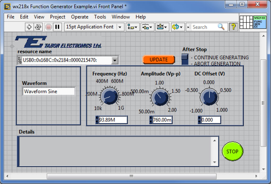
Use the ‘Update’ button to write the parameters you change or use the cursors to change them on the fly. Use the ‘Stop’ button to finish and close the operation of this example. If the ‘Abort Generation’ option is chosen, then after you will press the ‘Stop’ button, the unit will perform a reset.
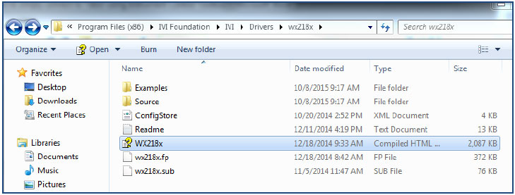
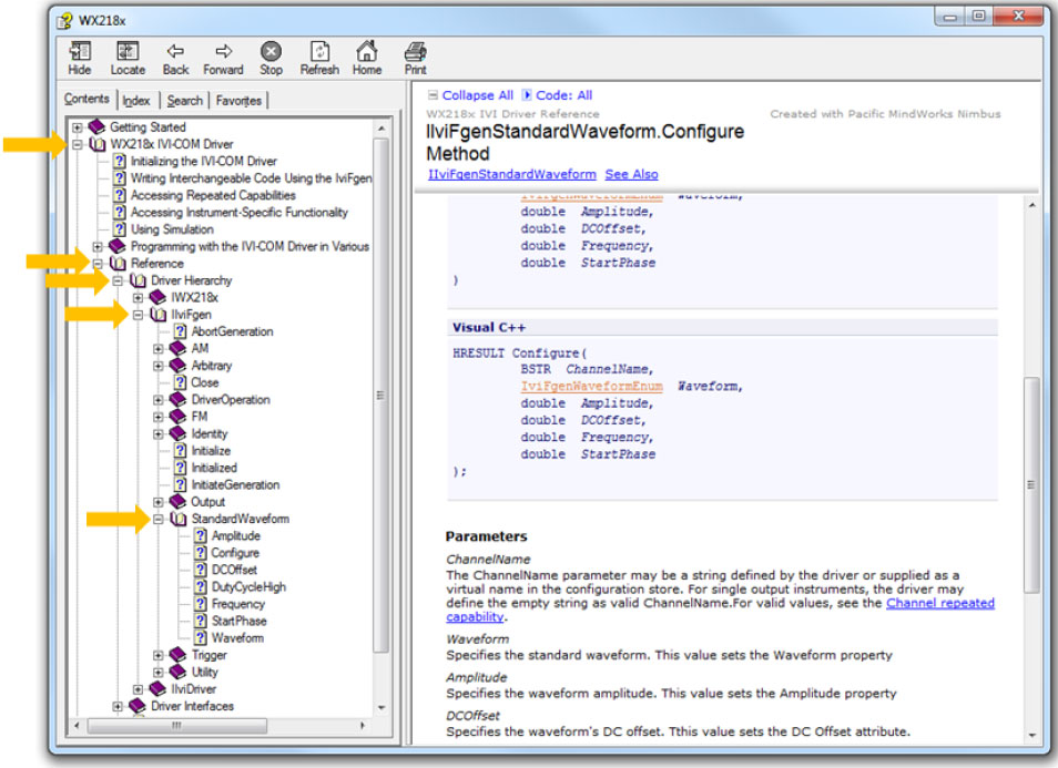
10. For more information regarding the IVI driver functions:
a. Go to: C:\Program Files (x86)\IVI Foundation\IVI\Drivers\wx218x & open the “WX218x” HTML file:
b. Follow the path as shown below:
In the next tutorials of the series “How to Control Tabor AWGs with LabVIEW”, we will show a few practical LabVIEW coding examples.
For More Information
To learn more about how to remote control Tabor instruments using LabVIEW, visit our website Support & Tutorials zone. If you encounter difficulties with connecting to Tabor units using LabVIEW, please contact us at [email protected] and our support team will gladly help. For more of Tabor’s solutions or to schedule a demo, please contact your local Tabor representative or email your request to [email protected]. More information can be found at our website at www.taborelec.com