In this tutorial, we will give an example on how to load a waveform file to Tabor AWG using the IVI driver.
If you haven’t been acquainted with controlling Tabor AWGs using LabVIEW, please refer to Tabor’s website for previous tutorials in the series ““How to Control Tabor AWGs with LabVIEW”:
- ‘Getting Started’.
- ‘Using SCPI Commands’.
- ‘Using the IVI Driver’.
For this tutorial, we will use LabVIEW 2015 32bit, wx218x 32bit IVI driver and a Tabor WX2184C using USB interface. To ensure you successfully established all the necessary settings for remote control over the Tabor instrument using LAN/USB/GPIB, please make sure you have already installed the latest NI-VISA from the National Instruments website. Also please go over the connectivity tutorials on the Tabor’s website.
- Load an Arbitrary Waveform File Using The IVI driver Functions
1. First, you will have to open a new VI:
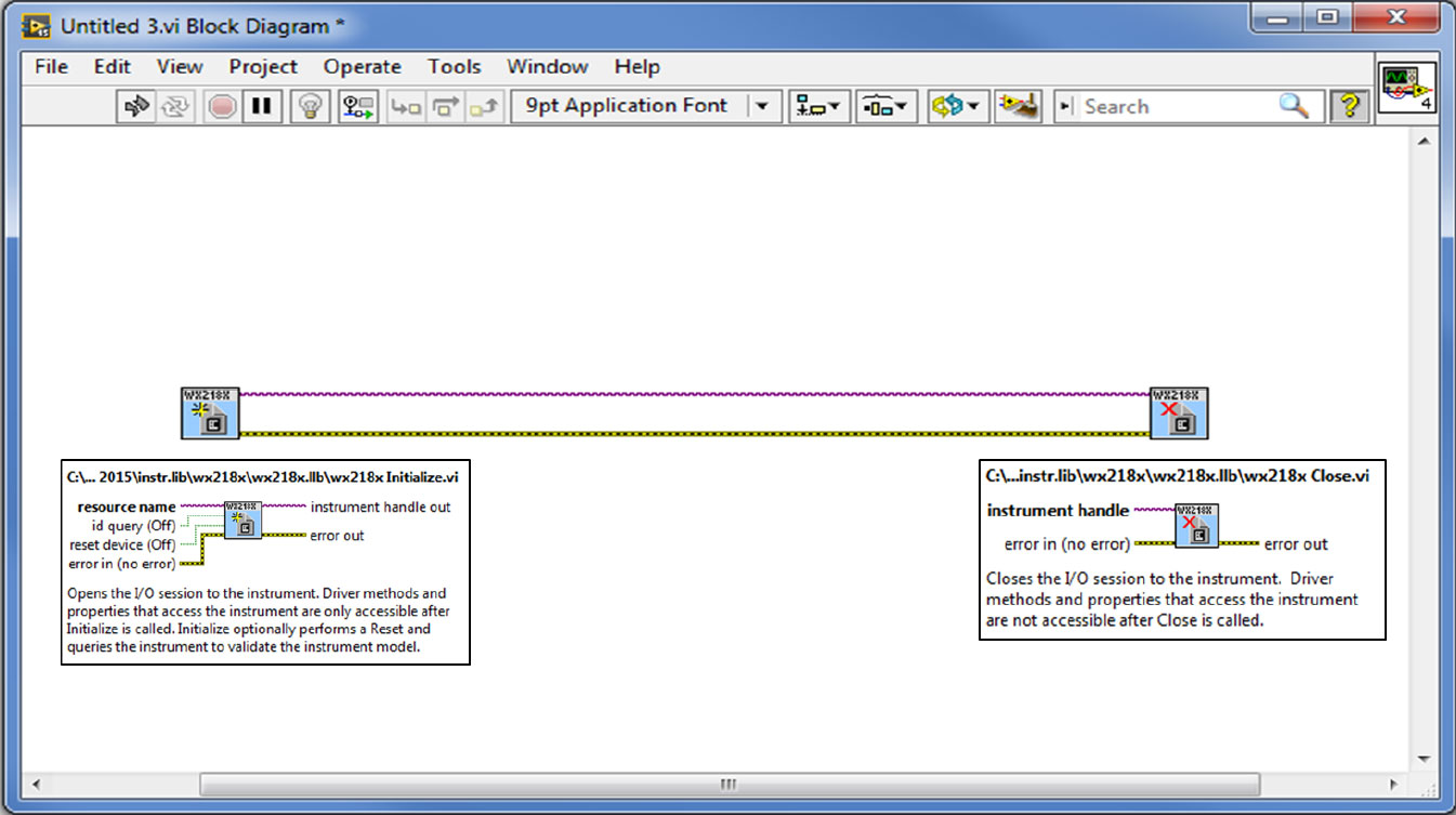
a. Drag & drop into it the ‘Initialize’ and ‘Close’ VIs. Wire them as can be seen below:
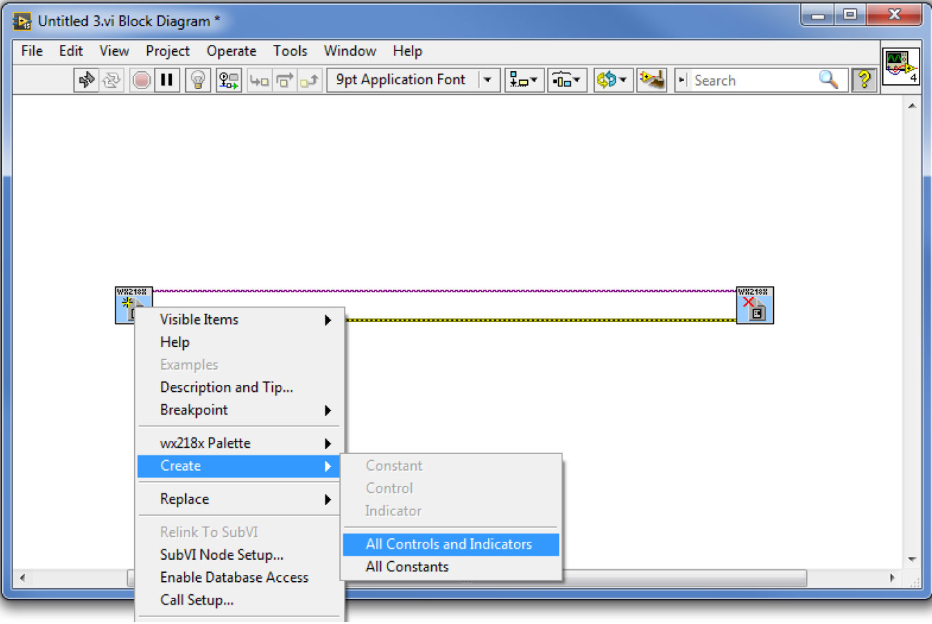
b. Right click on the ‘Initialize’ VI, choose to create all controls and indicators:
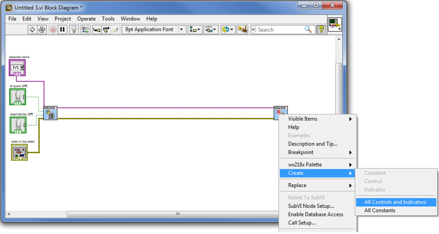
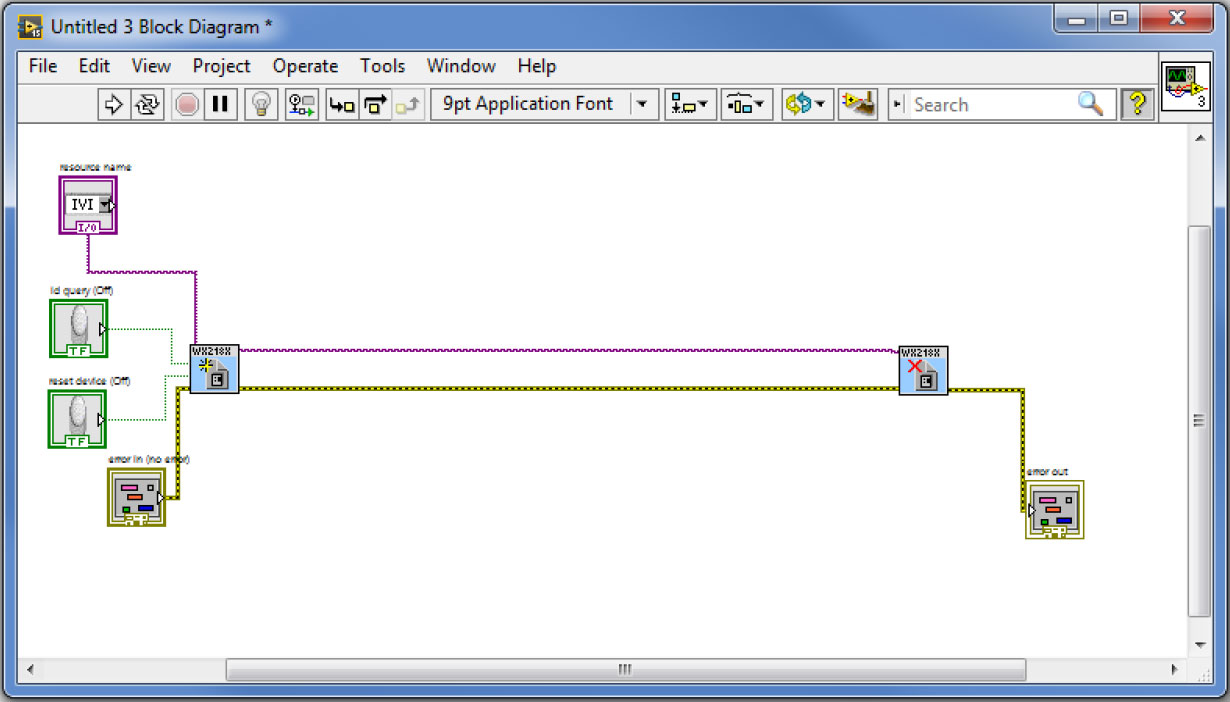
c. Do the same for the ‘Close VI:
From hereafter, between each step, you can try to run the code to make sure each VI is working properly. At the end of each run just press the ‘LOCAL’ (ESC) soft key button on the Tabor AWG’s front panel to make sure the proper settings were made to the instrument.
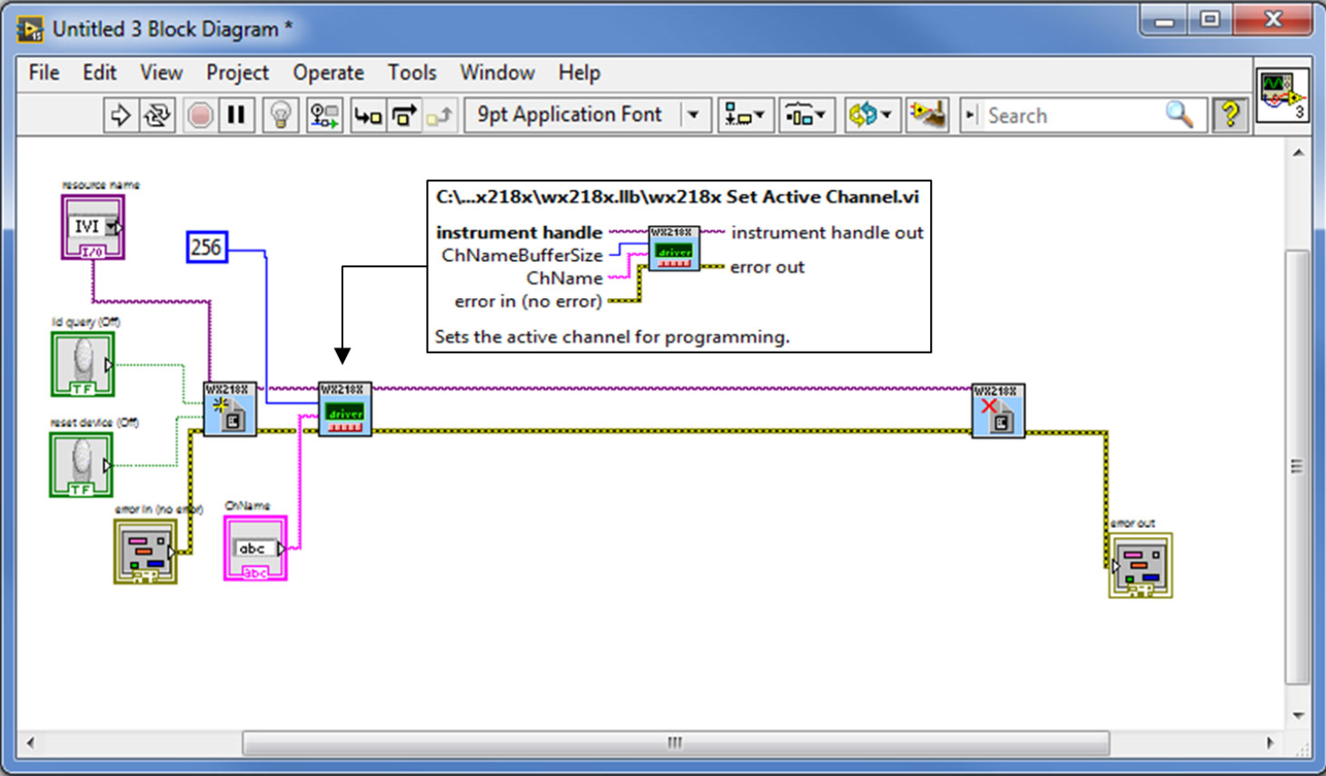
2. Add the ‘Set Active Channel’ VI and wire it as can be seen below. Create its ‘ChName’ control and ‘ChNameBufferSize’ constant:
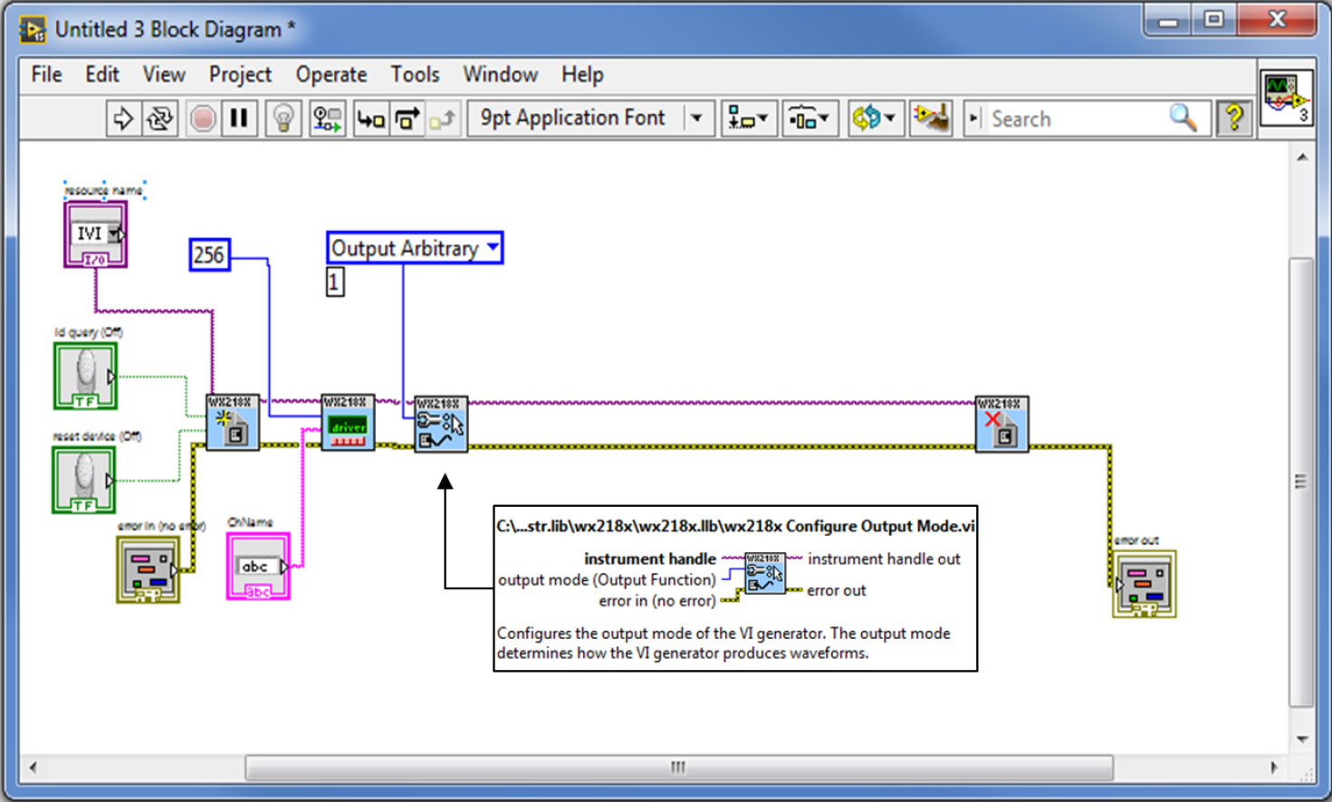
3. Add the ‘Configure Output Mode’ and wire it as can be seen below. Create its control:
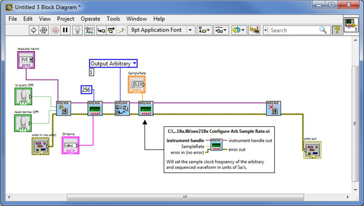
4. Add the ‘Configure Arb Sample Rate’ VI, wire it and create its control as seen below:
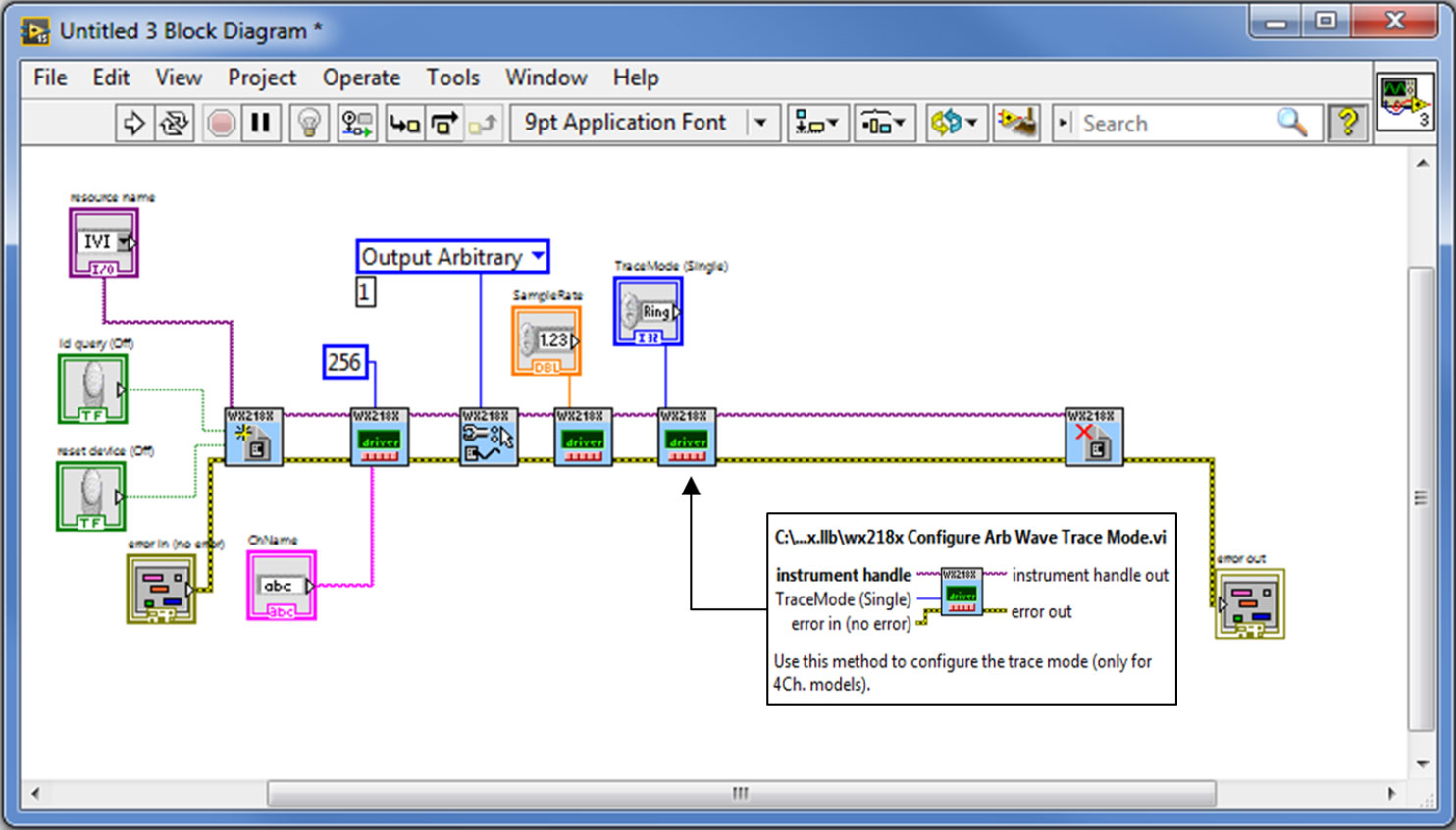
5. Add the ‘Configure Arb Wave Trace Mode’ VI, wire it and create its control as seen below (this VI should be added only in case you are using a WX2184C unit):
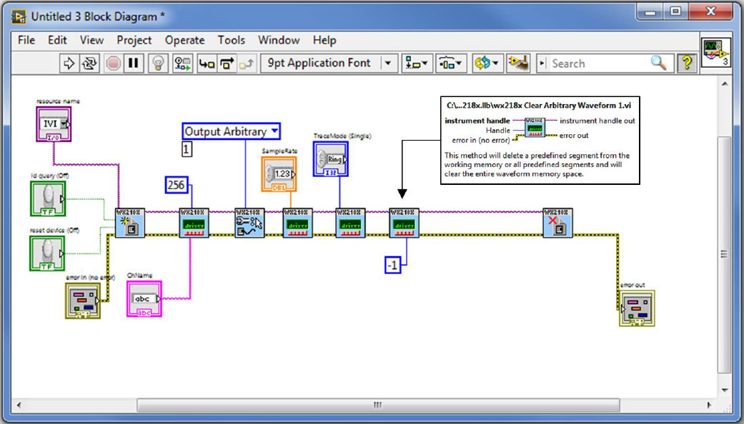
6. Add the ‘Clear Arbitrary Waveform 1’ VI, wire it and create its constant as seen below:
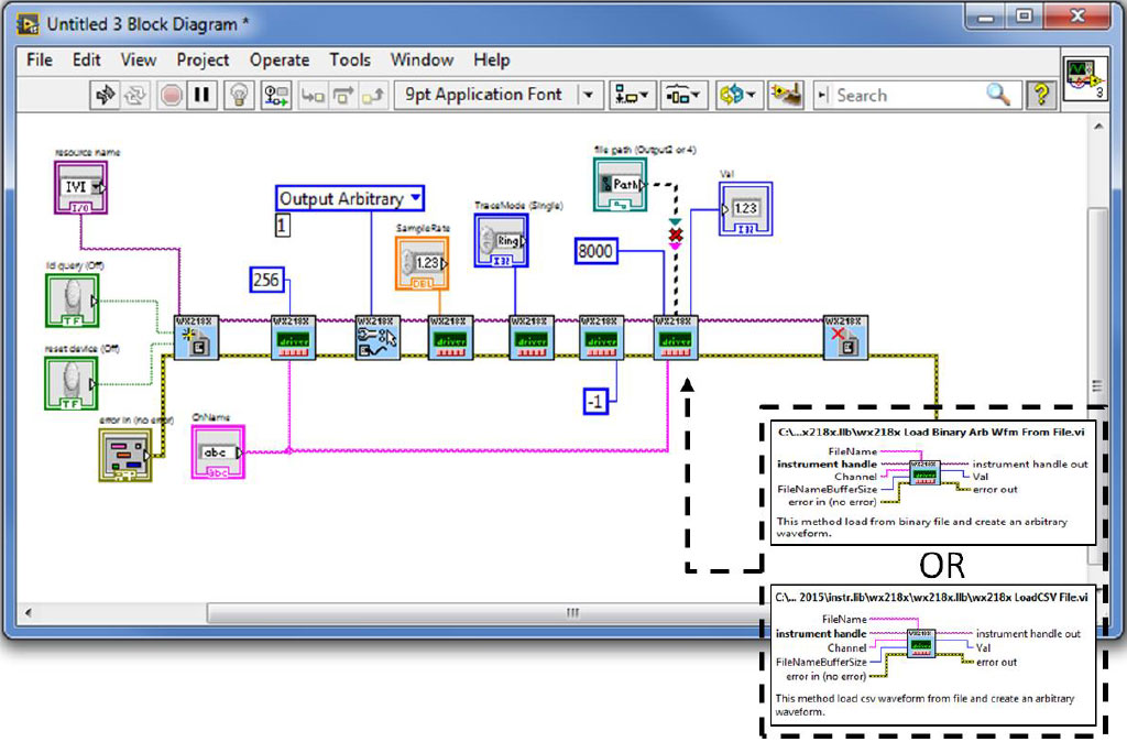
7. Add the ‘Load Binary Arb Wfm From File’ VI, wire it and create its control, constant and indicator as seen below. This VI can download waveforms as *.wav files. There is a similar VI which allows you to do the same using a *.csv file (‘Load CSV File.vi’) which will be connected the same way:
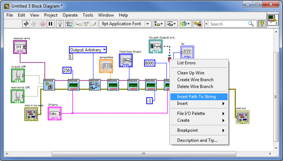
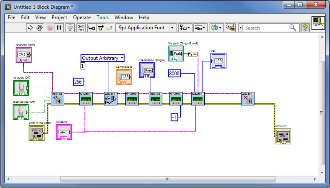
Right click on the broken wire and choose to insert Path to String:
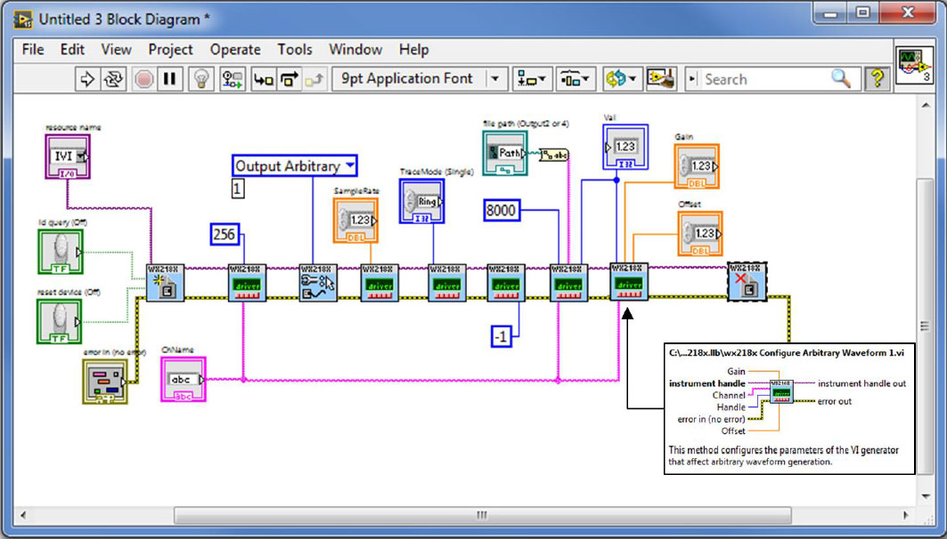
8. Add the ‘Configure Arbitrary Waveform 1’ VI, wire it and create its controls as can be seen below:
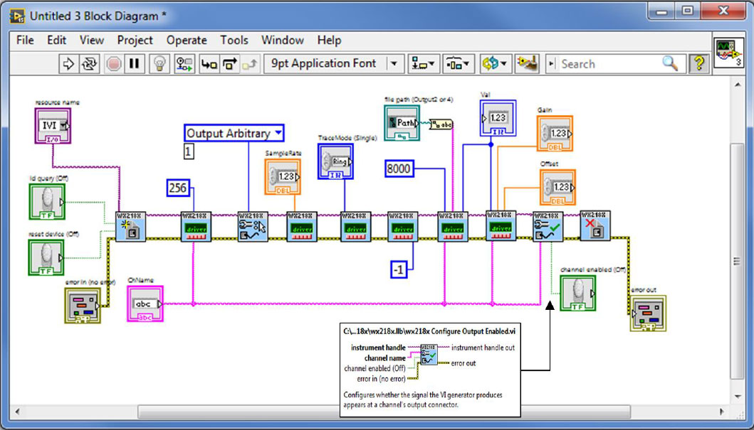
9. Add the ‘Configure Output Enabled’ VI, wire it and create its control:
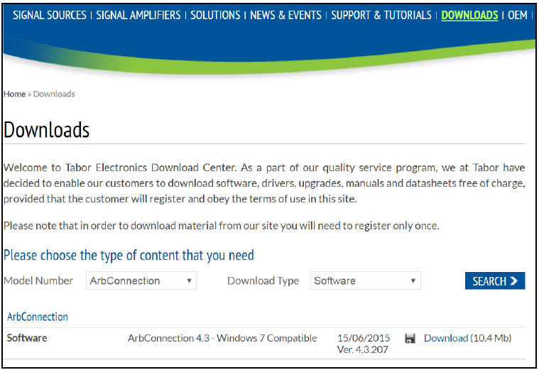
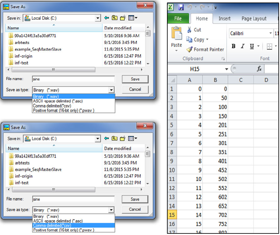
10. In order to test the created example, you will need to create a *.wav or *.csv files with binary data. One easy way of creating such files is using ArbConnection, Tabor’s free software, which could be downloaded from Tabor website’s download section:
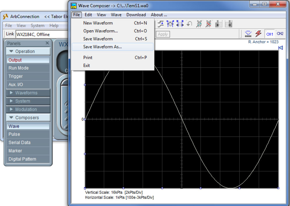
Using ArbConnection you can also save the composed waveform in several file formats including *.csv:
11. Go to the VI’s front panel and fill in the required setting as can be seen below:
a. Choose the correct resource address
b. Choose the path for the file you wish to download
c. Set the active channel to be ‘Channel1’
d. Assign to the amplitude a certain value (within the instrument’s specification). Set the offset
e. Set the Channel’s Output to ‘ON’
f. Set the sample rate clock to 2GS/s
g. Choose to work with ‘Duplicate’ download method (only for WX2184, WX2184C)
h. Press the ‘Run’ button
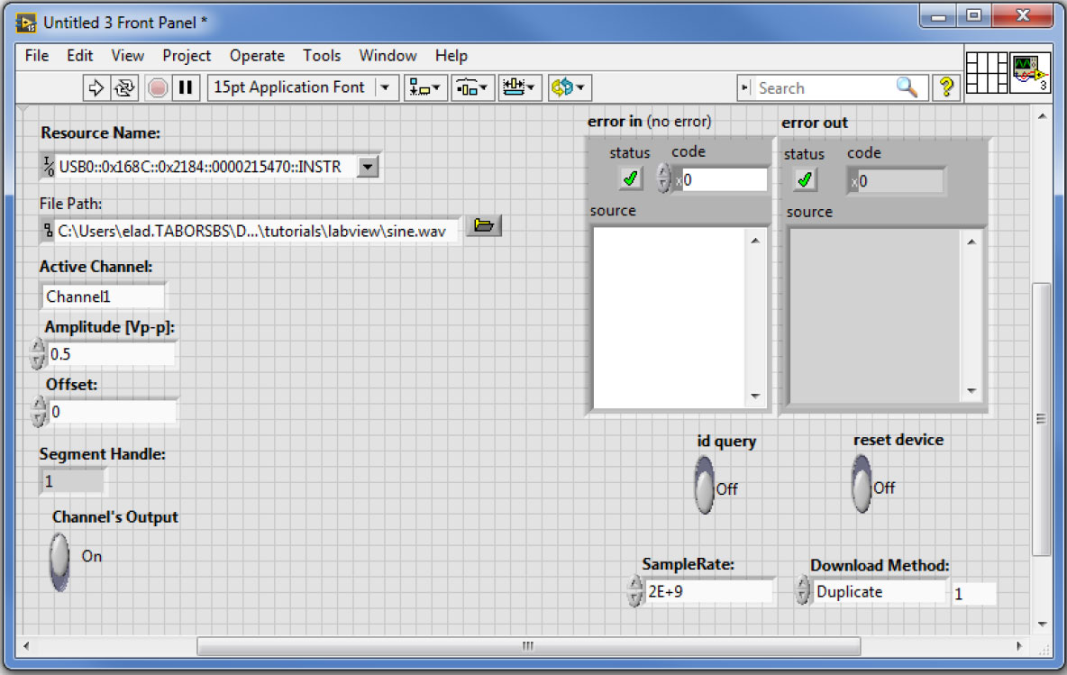
Once you will run this example, a segment handle will appear on the ‘Segment Handle’ indicator.
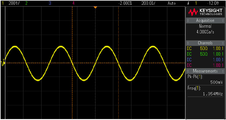
12. Using Tabor Arbitrary mode we have control over the output signal frequency as follows:
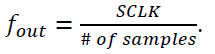
The ‘sine.wav’ (or ‘sine.csv’) file holds 1024 samples. The SCLK was set to 2Gs/s, so we would expect to get a 1.953MHz sine wave as can be seen on scope:
13. This step is relevant for a WX1284/ WX2184/ WX1284C/ WX2184C units only:
The ‘Download method’ you will choose to work with, will define how arbitrary waveforms will download to the unit’s memory. The channel pair memory block is divided in such a way that the individual channel’s memory blocks (16Mpoints per channel in standard configuration) are interleaved in blocks of 16 points.
As a result of the shared memory block, the segment size of each channel in a channel pair must be identical. In addition, when downloading data, it is ALWAYS written to the shared memory block and therefore to both channels. The user has two ways of downloading the waveform data:
- COMBINED – The Tabor AWG assumes the user is downloading to both channels and has pre-arranged the data in the required 16point interleaved manner. This is the COMBINED download mode and it is the fastest way to download data to the unit. Note that in this mode the user has full control so waveform data must be arranged correctly.
- SINGLE, DUPLICATE, ZEROED - This second option allows the user to prepare the waveform as if each channel memory is independent and once the data is transferred, the unit itself will arrange the data in the memory. There are 3 modes where the unit handles how the data is written:
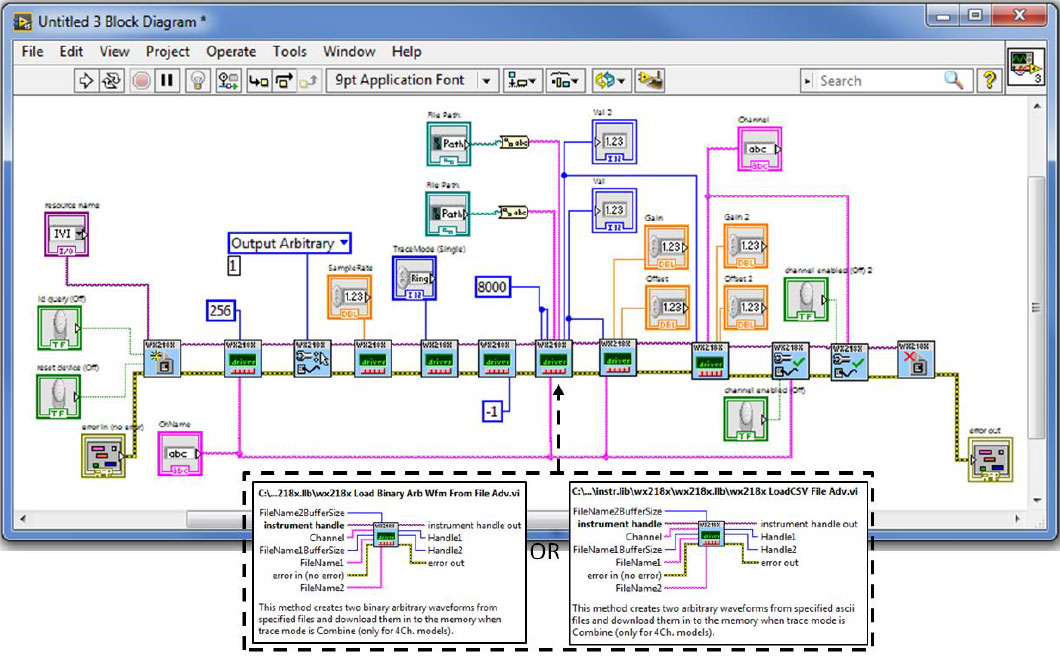
In order to download different waveforms to a channel pair, please use the the ‘Load Binary Arb Wfm From File Adv’ or the ‘LoadCSV File Adv’ VIs, which automatically arranges the two input files in the required 16point interleaved manner. Wire & create the required controls constants and indicators as can be seen below :
Go to the VI’s front panel and fill in the required setting as can be seen below:
a. Choose the correct resource address
b. Choose the paths for the files you wish to download. Make sure they are with the same length
c. Set the Primary channel to be ‘Channel1’ and secondary to ‘channel2’ (or primary to ‘Channel3’ and secondary to ‘Channel4’)
d. Assign to each channel’s amplitude a certain value (within the instrument’s specification). Set the offset
e. Set each of the Channel Outputs to ‘ON’
f. Set the sample rate clock to 2GS/s
g. Choose to work with ‘Combine’ download method
h. Press the ‘Run’ button
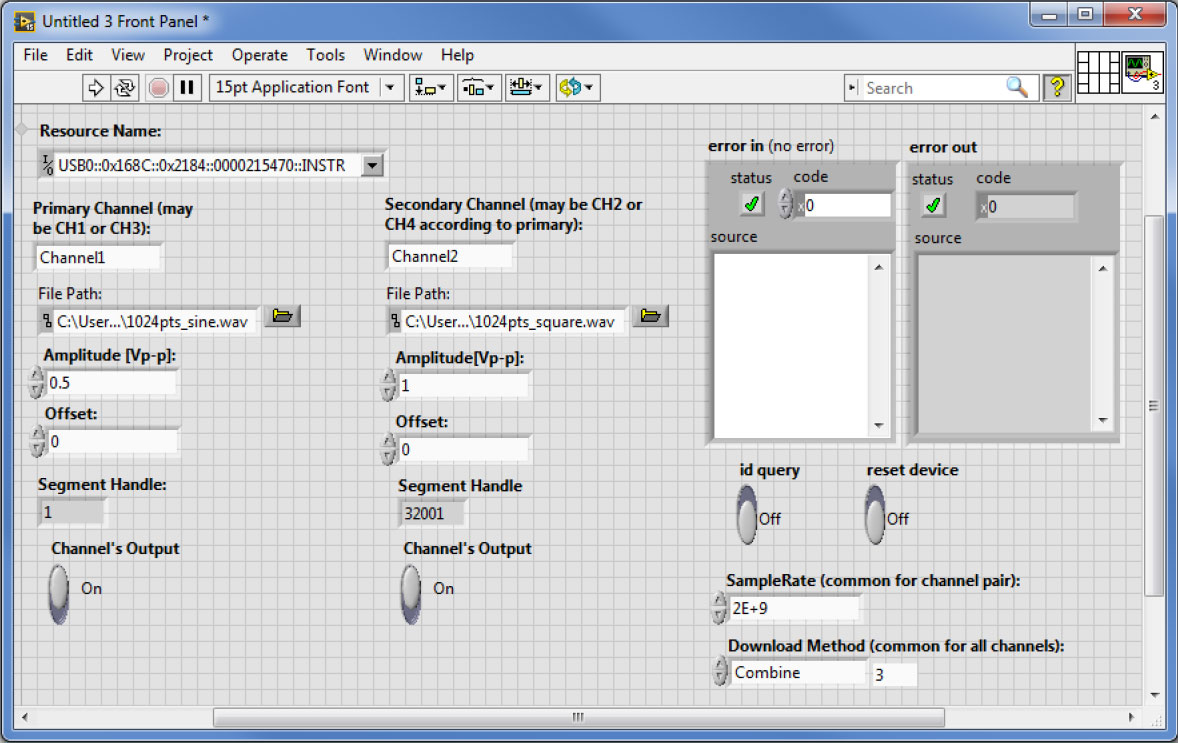
As the max number of segments you can create for each channel is 32,000, the first segment handle created for CH2 starts with 32001.
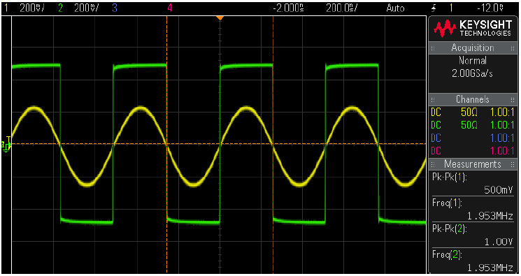
We would expect to get a 1.953MHz 0.5Vp-p sine wave & a 1.953MHz 1Vp-p square wave as can be seen on scope:
Attached to this tutorial you will find the corresponding VI, saved as LabVIEW 2013 format.
In the next tutorials, we will show 3 more examples:
- Example #2: Generate A Sequence Of 3 Waveform Files Using The IVI Driver Functions.
- Example #3: Synchronize Between Two Tabor AWGs Using The IVI Driver Functions.
- Example #4: Create an arbitrary waveform from binary data.
For More Information
To learn more about how to remote control Tabor instruments using LabVIEW, visit our website Support & Tutorials zone. If you encounter difficulties with connecting to Tabor units using LabVIEW, please contact us at [email protected] and our support team will gladly help. For more of Tabor’s solutions or to schedule a demo, please contact your local Tabor representative or email your request to [email protected]. More information can be found at our website at www.taborelec.com