Introduction
A mixer is a usually a three port passive device used for frequency translation. In the Frequency Domain it adds and subtracts two frequencies together. In the time domain it is the equivalent of multiplying two sinusoids of specific frequencies together. Generally, one frequency is defined as the Local Oscillator (LO) and the other frequency is the Intermediate Frequency (IF). Referring to figure 1, when the LO is applied the positive swing turns on green half of the bridge and the negative swing turns on the yellow half, thus only allowing the input frequency current to flow during these on and off times. If the LO frequency is much greater than the IF, which is usually the case, the high frequency switching of the diode circuit produces a time domain envelop of the lower frequency, or effectively adding the LO and the IF.
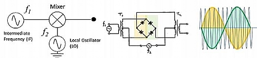
Figure 1. A balanced mixer
Using transformers on the input creates a balanced design. A single balanced mixer suppresses either the local oscillator or the signal input at the output, but not both. While a double balanced mixer (the most common) has both its inputs applied to differential circuits, so that neither of the input signals appear at the output, only the product signal. In reality you get some amount of feedthrough, specified as LO-RF Isolation.
In this application note we will use a Quantum Microwave 5.3GHz to 16GHz Image reject mixer. This is a single sideband mixer. A process of splitting the LO into two signals, one in phase and one quadrature, means that one sideband will be the summation of LO and IF frequencies, while the frequency (and phase) of the other sideband, is the difference of the LO and IF frequencies.
The key Specifications are as follows:
- Frequency Range: 5.3GHz - 16GHz
- Conversion Loss: 10db Max
- IF Bandwidth: 20MHz – 100MHz (Integrated IF Filter)
- LO Power: 10dBm
- LO to RF Isolation: -40dBc
- Reject Upper Side Band 20dB min
Measurement Setup
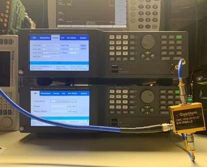
The Lucid LS1294B four channel 12GHz Analog Signal Generator is ideal for mixer testing as it is essentially four independent signal generators in a single benchtop formfactor instrument. We can use one channel to generate the LO and the other channel to generate to the IF. The LS1294B is ideal as it can generate enough power on one channel to drive the LO as required, while generating on the second an appropriate IF frequency and amplitude. For these measurements we have channel 1 set to 6GHz with 10dBm of power and channel 2 set to 50Mhz and the power level is 0dBm. Channel 3 can be used in conjunction with Channel 2 to pride two-tones at the IF input for TOI measurements. The measurement setup is shown in Figure 2.
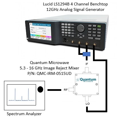
Figure 2. Mixer Measurement Setup using the LS1294B.
As our LO is set to 6GHz and the IF is set to 50GHz ,we will see two sidebands around 6GHz. A Quantum Microwave mixer of this type has been optimized to suppress both the carrier and the adjacent image signal, thus relaxing receiver filtering requirements. Figure 3.
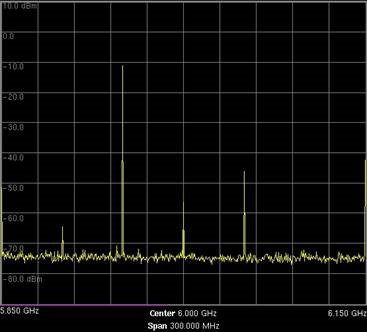
Figure 3 – LO 6GHz, IF 50MHz with lower sideband image rejection.
Conversion Loss
This is the measure of how well mixer provides frequency translation from the IF input signal to the RF output signal. Channel 1 of the LS1282B is our IF signal and is tuned to 50MHz with a power level of 0dBm. Channel 2, our LO, is tuned to 6GHz. Conversion loss of a mixer is equal to the IF input power minus the RF single sideband output power expressed as a positive number in dB – in this case our IF is 0dBm and the measured single side band power is -10dBm.
In a mixer used for up-conversion,
Conversion Loss (dB) = Power at input IF frequency in dBm - Power at output RF frequency in dBm
Or 0 dBm – (-10dBm) – 10dB.
If the mixer is used for down-conversion,
Conversion Loss (dB) = Power at output RF frequency in dBm - Power at input IF frequency in dBm.
Conversion Loss Over Frequency
Using the frequency sweep function of the LS1292B, while the spectrum analyzer trace is set to peak hold, provides a conversion loss plot – see figure 4.
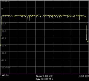
Figure 4 – measured conversion loss over a 690MHz LO Sweep.
Isolation
Isolation is a measure of the circuit balance within the mixer. The LO-RF or RF-LO isolation can be seen as the leakage of the LO signal into the RF port and is the difference in power between the input signal and the leaked power to the other ports. Referring to Figure 3 we measure the LO signal at 6GHz at the RF port as 55dBm. As the LO input was 10dBm the Isolation between ports is -65dBc.
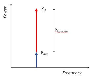
Figure 5 – LO Feedthrough or LO to RF Isolation
IF Frequency Response
Conversely to sweeping the LO in to determine conversion loss over our frequency of interest we can sweep our IF frequency to determine the frequency response of the IF. The Quantum Microwave Mixer has 20MHz to 100MHz IF bandwidth. Figure 6 shows the results of sweeping the IF.
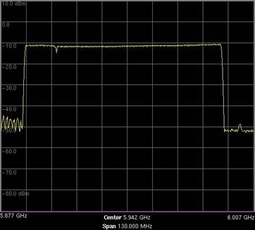
Figure 6 Sweeping the IF Frequency
Intermodulation - Two Tone, TOI Measurements
Intermodulation is caused by two or more carriers constructively interfering with each other and creating frequency related sidebands. For every dB increase in the fundamental the intermodulation products increase by two (second order) or three dB’s (third order). Third order harmonics are in the form of 2f1 - f2 and 2f2 – f1, and an example of a second order intermodulation product would be f2-f1, f2+f1. As we are fundamentally dealing with a non-linear device and in most cases the signal will be modulated, understanding how the mixer performs at its output with multiple varying input frequencies and amplitudes, is key.
Using CH 3 of the Lucid LS1294B allows us to create a second tone we can sum with our original IF signal at the input of the mixer. Calculating and observing where each intermodulation sideband falls with varying input power levels, allows us to understand how to optimally set the input power of the mixer.
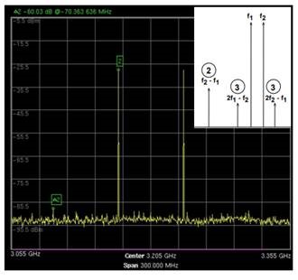
Figure 7 Intermodulation Sidebands
The Benchtop version of the Lucid series offers up to 4 phase coherent channels in a 2U 19” benchtop box. With a 5” touch display and front panel control buttons, the Benchtop platform enables users to program the instrument without the need of an external PC. For synchronized, phase coherent, multi-channel applications such as quantum physics and phased array antennas the Benchtop platform is an ideal, high performance and cost-effective solution.
- 3,6 and 12GHz RF Analog signal Generators
- Extremely fast switching speed of <100us
- Single, dual and four phase coherent channels in a single box
- Remotely programmable via MATLAB, Python, LabView and other software programming environments
- Easy to use benchtop platform with 5'' touch screen and user-friendly GUI
- Exceptionally low phase noise of -145dBc/Hz @100MHz and 10kHz offset
- Small form factor and space efficient benchtop platform
- AM, FM, PM Sweep & Pulse Modulation
- Removable SD card for instrument security
For more information: [email protected]