Extending the architecture of the Computer / Controller
PXI or PCI eXtension for Instruments was introduced to the market in 1997, as an effort to reduce the overhead of connectivity standards, such as GP-IB and LAN eXtensions for Instruments (LXI). Fundamentally the instrument directly becomes part of the computer’s architecture much like an addition of an advanced video processor, or an extra processing unit such as a GPU. While the latter two systems would be contained within the computer, PXI extends the bus to an external chassis, that houses measurement/instrumentation cards as shown in Figure 1. The PXI measurement/instrumentation cards were original defined as 3U and 6U card sizes, however, the industry today is dominated by the 3U card standard.

Figure 1 – PCI extends the computer's PCI bus to an external instrument chassis that houses instrumentation cards.
PXI Standards Evolution
PXI tracks the PCI bus standard, as it provides the fundamental electrical and software protocol element of the connectivity system. It is important to note, that PCI and therefore PXI has evolved over time resulting in two versions that are not backward compatible with each other – PXI and PXIe (Extended). Both versions are relevant and suit different application vs. cost needs. In general, if the application requires moving large amounts of data from the instrumentation to the processor or vice versa at high speed with low latency then PXIe would be the logical choice. If the application is low bandwidth with no speed or latency requirement then PXI will suffice. Table 1 gives examples of different instrument types that utilize the different buses.
|
PXI
|
PXIe
|
|
Mechanical Switching
|
Real time receivers and spectrum analyzers
|
|
Amplifiers
|
High Speed digitizers
|
|
Arbitrary Function Generators
|
Arbitrary Waveform Generators
|
Table 1 Typical types of instruments using PXI or PXIe.
PXIe Evolution
PXIe has also evolved through several iterations or ‘generations’, called Gen 1, 2, 3, etc. Gen 1 had provided a speed of 250MB/s, (250 MegaBytes per Second) while Gen 3 provides 984.6MB/s of throughput. It is essentially a four-wire differential system: two differential lines are for transmission and two differential lines are used for reception. Speeds are increased by using multiple lanes in parallel. For example, Gen 3 x2 (generation three, two lanes) - provides 1.969GB/s of throughput. Table 2 compares the different generations and lane configurations of the standard. It is important to note that all generations are compatible with each other, and fewer lanes can be used if they’re not available.
| |
x1
|
x4
|
x8
|
|
Gen 1
|
250MB/s
|
1GB/s
|
2GB/s
|
|
Gen 2
|
500MB/s
|
2GB/s
|
4GB/s
|
|
Gen 3
|
984.6MB/s
|
3.94GB/s
|
7.88GB/s
|
Table 2 Comparison of PCIe generations and lane usage.
Compared to Ethernet 1000Base-T that has a throughput of 125MB/s PXIe/PCIe provides significant advantages in data transfer speeds.
Chassis and Backplanes
A chassis is usually defined by the number of card slots (defining the width of the chassis) if it’s PCI or PCIe (or both - Hybrid), the generation of PCIe, and the number of lanes available on the backplane. As discussed, earlier PXI and PXIe are not backwards compatible and have different backplane connectors. In some chassis, there is also a system slot for either a computer controller module or an interface card to extend the bus back to the PC controller. If there are no controller slots, then connectivity to the controller is through a connector on the rear of the chassis. Figure 2 shows the different potential connector configurations that define the operation - PXI, PXIe, or Hybrid.
 Figure 2 – Chassis Backplane Connector configurations.
For PXI the upper connector takes advantage of backplane triggering and timing capability, while the second lower connector is the 32bit PCI parallel bus. For PCIe, the lower PXI connector is omitted, and the upper portion contains two connectors as opposed to the single connector used for PXI. A Hybrid slot can take both a PXI card and a PXIe card. However, the PXI card must not have the upper trigger connector installed, as it will not physically fit.
Usually, a chassis will define the slot usage with some symbols - a circle indicating it’s for a measurement card and a triangle indicating it is a system card slot. Hybrid card slots are denoted by a superscript ‘H’. Chassis are available in all configurations of slots, some may contain all three connector types, some may be PXI only or PXIe only.
Measurement Cards
The physical size of the cards for PXI and PXIe are identical, however, attention needs to be paid to the connectors on the rear of each card.
For PXI there are two types of measurement cards - the first uses two connectors. As mention previously the upper connector takes advantage of backplane triggering and timing capability, while the second lower connector is the 32bit PCI parallel bus. The second type of card uses only the PCI bus so only the bottom connector is required.
For PXIe instruments there are two connectors at the top of the card that take the same physical space as the upper single PXI connector mentioned in the previous paragraph. The lower of the two PXIe connecters contains the PCIe lanes.
Figure 3 compares the two flavors of PXI card and the PXIe card connectors.

Figure 3 – A comparison of PXI and PXIe cards and their backplane connectors.
Connecting to the Computer PCI, PCIe or MXI
Connection to the controller computer can be through a PCI/PCIe cable, or in most cases, an MXI connection is employed. MXI or Multisystem eXtension Interface for PCI is a connectivity enhancement, that allows connectivity of multiple chassis to a single computer, either through multiple MXI connectors on the controller computer, or by daisy chaining multiple chassis together.
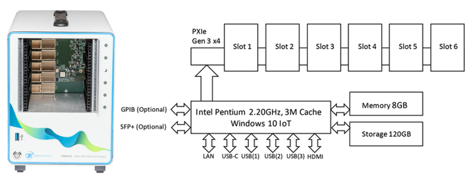
The PXE6410
The PXE6410 is a PXIe based 6 based slot Gen 3 x4 chassis, that supports the Tabor Proteus Family of PXIe AWG’s and the TE330x family of PXIe RF amplifiers. The Chassis allows you to purchase any Proteus PXIe module and later add or up-grade to more channels, higher sample rates or higher output power. The system includes an embedded PC with an internal SSD drive, HDMI connection, USB interfaces for a mouse and keyboard, as well as control using USB-C and 1000BASE-T LAN.
Target Applications
An ideal solution for designing modular, scalable control systems for quantum computing, closed loop Electronic Warfare, Radar Target Generation and for prototyping multi-channel MIMO communications systems, the PXE6410 combined with advanced direct RF Arbitrary Waveform Transceivers such as the P9484M-AWT helps solve the most demanding instrumentation integration problems.
For more information contact [email protected]