
Introduction
Amplification is an increase in size of a signal by some factor which is greater than 1. One would require an amplifier in a system where the signal source being used does not provide the required output level.
Generally speaking, there are several considerations one must take into account when deciding to acquire a new signal amplifier. This tutorial will address the topics which are most related to Tabor’s line of signal amplifiers as well as tips for selecting the most suitable amplifier for your application. It will also explain how each of the following topics, would influence the amplifier’s performance:
- Input & Output Impedance
- Gain
- Bandwidth (BW)
- Slew Rate (SR)
- Total Harmonic Distortion (THD)
- Load
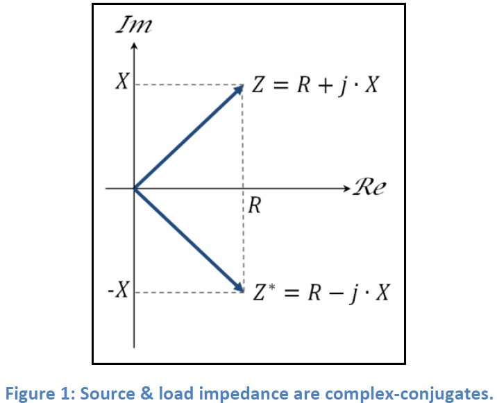
Input & Output Impedance Impedance has a real part which is frequency-independent (R = Resistance) & an Imaginary part which is frequency-dependent (X = Reactance):
𝑍=𝑅𝑒{𝑍}+𝑗∙𝐼𝑚{𝑍}=𝑅+𝑗∙𝑋
In order to maximize power transfer or minimize signal reflection from load to source, the input impedance of a source must match the output impedance of the load. Max power transfer is obtained when:
𝑍𝑠𝑜𝑢𝑟𝑐𝑒=𝑍𝑙𝑜𝑎𝑑∗
𝑅𝑠𝑜𝑢𝑟𝑐𝑒+𝑗∙𝑋𝑠𝑜𝑢𝑟𝑐𝑒=𝑅𝑙𝑜𝑎𝑑−𝑗∙𝑋𝑙𝑜𝑎𝑑
In cases where impedances are purely resistive (𝑋=0), then:
𝑅𝑠𝑜𝑢𝑟𝑐𝑒=𝑅𝑙𝑜𝑎𝑑
It is common practice for signal sources & signal amplifiers to match with the commonly used 50Ω coax cables. Therefore, a 50Ω input impedance is an available option on most of Tabor amplifiers except the High-Voltage amplifiers series, which use impedance bridging as an alternative to impedance matching.
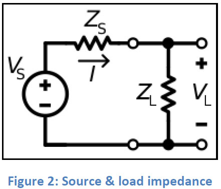
With impedance bridging, the goal is maximum voltage transfer rather than power. In such a case, amplifiers will have high (ideally infinite) input impedance and low (ideally zero) output impedance:
𝑍𝑙𝑜𝑎𝑑≫𝑍𝑠𝑜𝑢𝑟𝑐𝑒
Let’s try to figure out what are the advantages of using impedance bridging (for the sake of simplicity let’s assume for now that impedance = resistance). According to Ohm’s law:
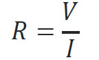
So the Impedance is the “ratio” between voltage and current:
With R=1Ω & I=1A, V=1V.
With R=50Ω & I=20mA, V=1V
With R=1MΩ & I=1μA, V=1V
Input impedance of an amplifier is a parameter which will help to determine how much current is required from the signal source in order to develop a certain amount of voltage at the amplifier’s input. In other words, what kind of change in current will lead to the desired change in voltage.
In case of a nominal voltage of 1V at the input of the amplifer, the measured current from the signal source is 1μA. When changing the voltage to be 2V, the measured current is 2μA. Now one can calculate the input impedance of this amplifier:
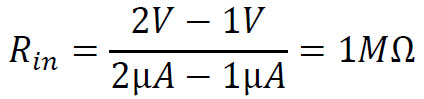
In cases where the input impedance is very high, the signal source is required to produce very low currents, therefore it will consume low power to develop the required voltage at the amplifier’s input. However, high input impedance may also limit the amplifier’s bandwidth.
The very same concept applies for the output of the amplifier, only now the source’s role is taken by the amplifier’s output. Minimizing the output impedance of the amplifier will help maximize the voltage being delivered to the load.
Gain
In electronics, gain is the ratio between the output and input of a certain measurement, voltage, power or current. In amplifiers, it is the ratio between the power of a signal at the amplifier’s output, to the power at its input. Amplification is simply a gain greater than one (or greater than zero dB) and is most commonly expressed in decibel units [dB]. The gain of an amplifier may vary with the frequency of the input signal and usually decreases as frequency increases.
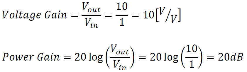
Voltage gain is simply the ratio between the output & input voltage of a signal:
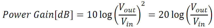
Power gain is expressed by:
Power gain can be calculated by using:
𝑃=𝑉2/𝑅
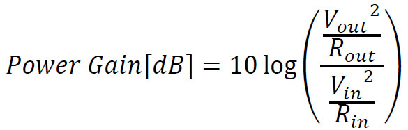
In cases where the input & output impedances are equal:
For example:
In case an amplifier has a 50Ω input impedance, and drives a 50Ω load with 𝑉𝑖𝑛=1𝑉 and 𝑉𝑜𝑢𝑡=10𝑉, it’s gain will be:
Bandwidth
Bandwidth is the difference between the highest and lowest frequencies in a band of frequencies and is measured in Hertz [Hz]. In some cases, it may refer to a passband bandwidth (difference between the high & low cut-off frequencies) and in other cases it may refer to baseband bandwidth (equal to the high cut-off frequency)
An amplifier’s bandwidth represents a continuous set of frequencies in which the amplifier is most effective at amplifying. In the case of Tabor’s amplifiers, it refers to the baseband bandwidth (DC to high cut-off frequency).
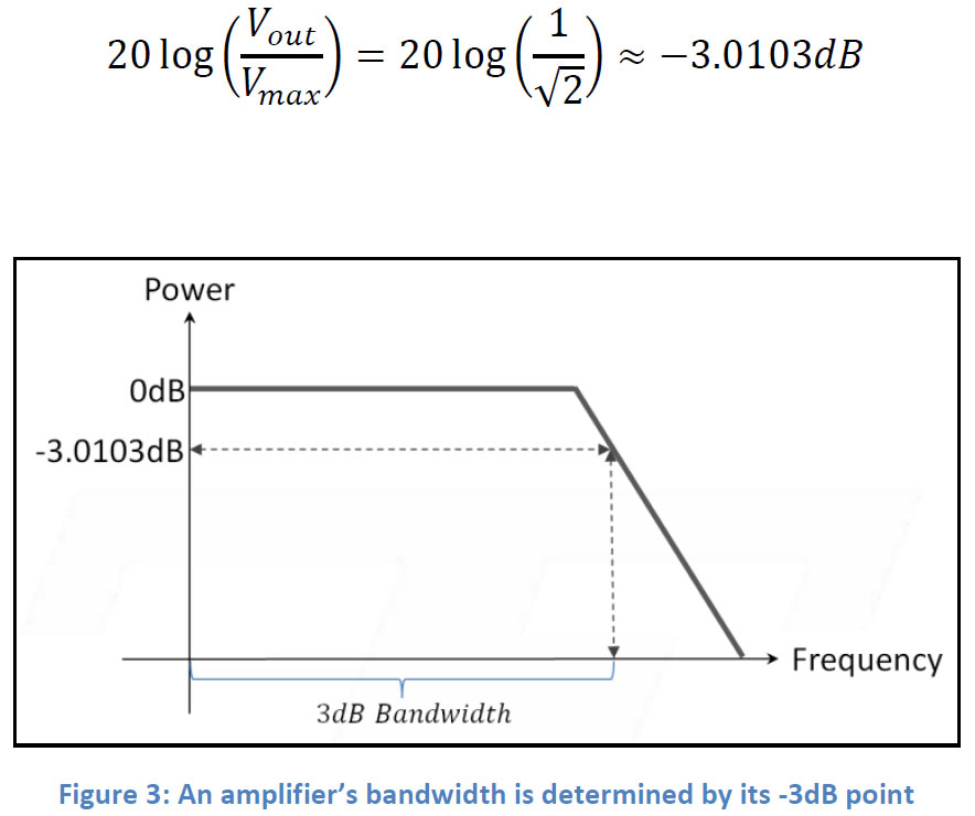
An amplifier’s cut-off frequency is most commonly expressed by the half-power point (also called the 3dB point) but may be expressed differently. When comparing specifications it is important to compare the same bandwidth specification. For example: one might make a mistake to compare a -3dB bandwidth specification with a -6dB bandwidth specification.
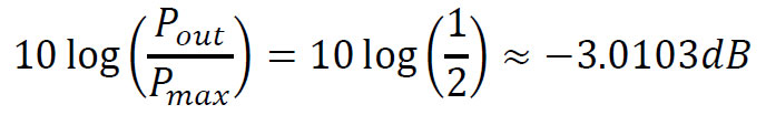
The half power point is the frequency at which the output power of an amplifier has dropped by half from its maximum value:
Or when the voltage has dropped by 29.3% of its maximum value:
Slew Rate
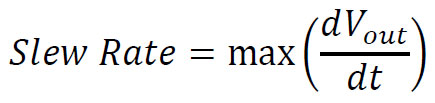
Non-ideal amplifiers have a maximum rate at which their output voltage may vary. This characteristic is called the voltage Slew Rate and is most commonly specified in volts per micro-second [V/μs]:
Slew rate will indicate how well the amplifier can track transitions of the input signal.
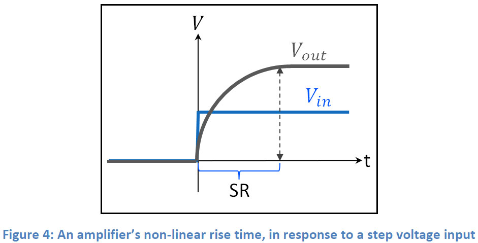
Why amplifiers have such limitation is beyond the scope of this paper, so let us assume that when an amplifier isn’t tracking changes “fast enough”, deformations to the signal’s shape will start to appear at its output. A good example for such deformation is a non-linear rise time effect in response to a step in voltage which exceeds the amplifier’s slew rate:
The load’s impedance will determine the maximum voltage swing, which is used to calculate the slew rate. Therefore, slew rate is affected by the load.
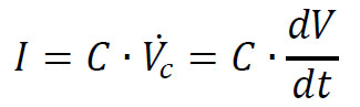
One example for such relationship is with capacitors. The below equation shows the relationship between the capacitance and the slew rate:
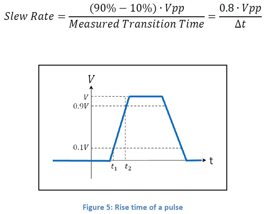
When calculating a slew rate for applications requiring generation of pulses, it is recommended to calculate slew rate using the rise time specification of the Tabor amplifier, in order to avoid undesired peaks in current:
Slew rate is usually specified with information on the setup it was measured with, including the impedance of the load used.
Here is an example of how to calculate the slew rate of a sine wave signal. We used the Tabor 9100A amplifier to output a 400Vp-p, @500kHz sine wave onto a purely resistive 1MΩ load:
𝑉𝑜𝑢𝑡=𝐴∙sin(2πf∙t)
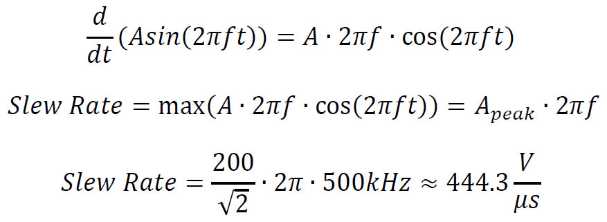
The 9100A’s specifications report a slew rate of ≈400𝑉/𝜇𝑠 , which corresponds with the calculations above.
Total Harmonic Distortion (THD)
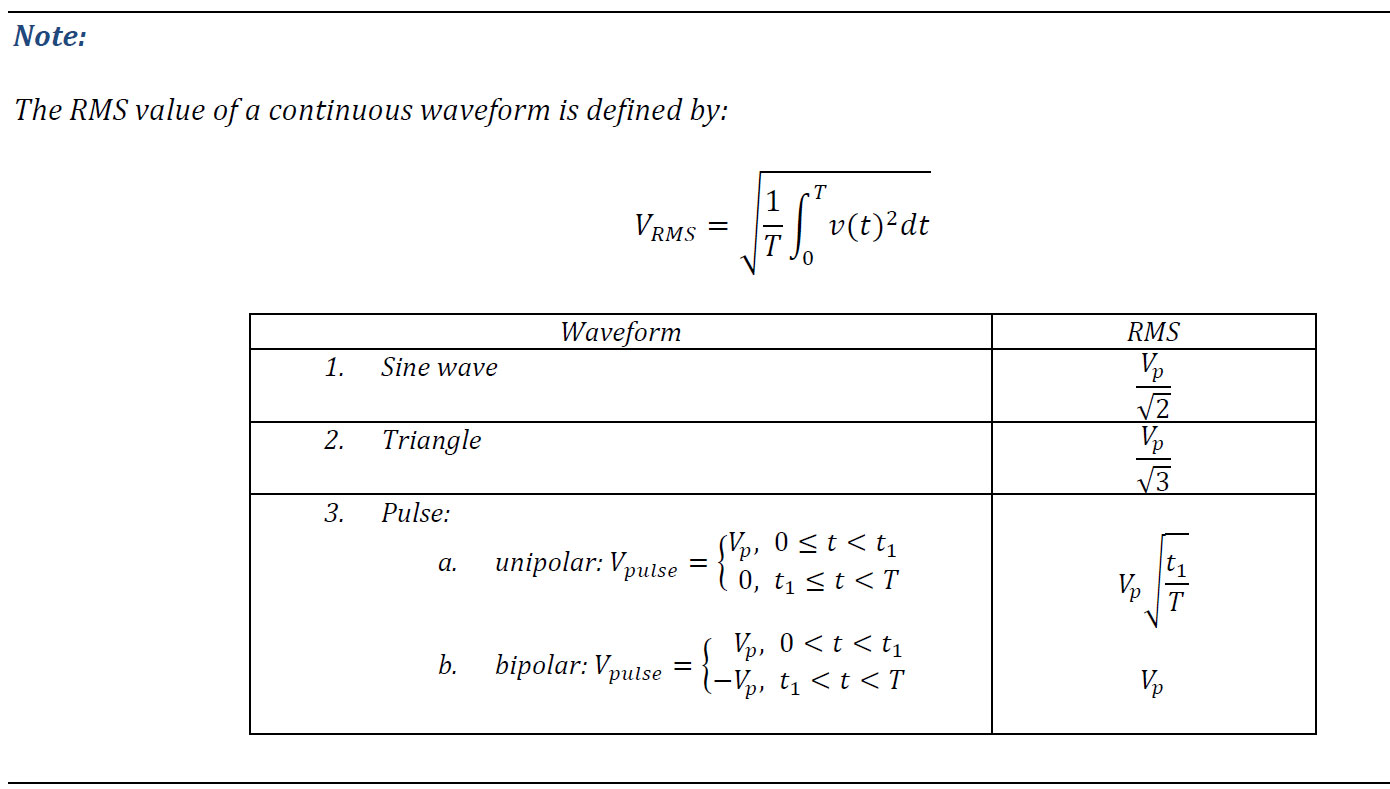
Total harmonic distortion is a measurement indicating how far the output signal is from generating a “pure” tone. The measurement is defined as the ratio between the RMS amplitude of a certain set of harmonics, to the RMS amplitude of the first harmonic (fundamental) of the same signal:
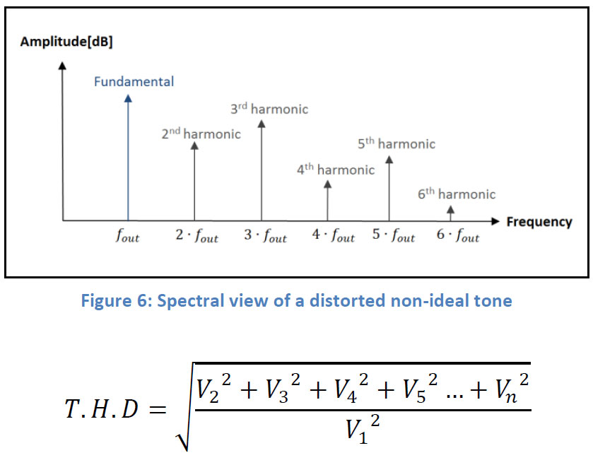
This measurement is most commonly expressed in percent [%] or [dB] and the lower it gets, the better is the signal’s purity. For example:
THD = 0.1% means that 0.1% of the output signal contains unwanted distortion.
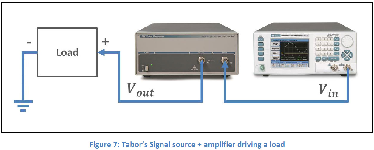
Load
Let’s examine how the impedance of a load may affect the amplifier’s max output current and bandwidth. An electrical component connected to the amplifier’s output will be referred to as the load. The load’s impedance will determine how much current is necessary to drive it. In most cases the current is limited by a certain value, in order to prevent possible damage to the amplifier.
According to Ohm’s law:
𝑉=𝐼∙𝑍
We know that impedance in its complex form is given by:
𝑍=𝑅𝑒{𝑍}+𝑗∙𝐼𝑚{𝑍}
Where, R (resistance) is the Real part & X (reactance) is the Imaginary part, the impedance’s magnitude is given by:
Impedance of a pure load will be:
Resistor:
𝑍𝑅=𝑅
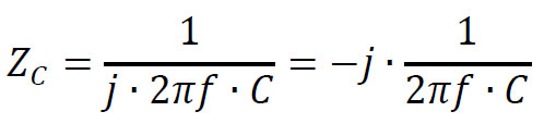
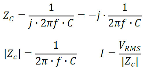
Capacitor:
Inductor:
𝑍𝐿=𝑗∙2𝜋𝑓∙𝐿
Loads with resistive nature
In cases where the load’s reactance may be neglected (in other words, purely resistive load), then it will be easy to determine the outputted current for a given voltage:
𝑉=𝐼∙𝑍𝑅=𝐼∙𝑅
Let’s pick the Tabor 9260 amplifier & a 50Ω resistor as our load. The Tabor 9260 amplifier has a maximum 1A current & 34Vp-p voltage limits at its output, assuming we are generating a sine wave:
Therefore, this will be a valid setup, as it won’t reach the amplifier’s current limit.
Loads with capacitive nature
Capacitive loads (in cases where the resistive part is negligible compared to the capacitive part) may be found in applications such as MEMS and Piezo electric devices (common examples include pressure sensors and MEMS mirrors) and require more careful attention.
As frequency increases, a capacitor’s reactance decreases, therefore higher current is required to develop the same nominal voltage. The same goes for the capacitance of the load. As it increases (while frequency remains constant), the reactance decreases and therefore, higher current will be required:
Say we use the Tabor’s 9200A amplifier, which has a 100mA current limitation (per channel) & would like to generate a 400Vp-p sine wave at 500kHz on a purely capacitive load:
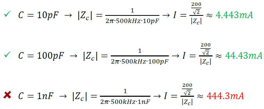
As can be seen above, C=1nF load @ 500kHz will exceed the 9200A’s maximum current limit.
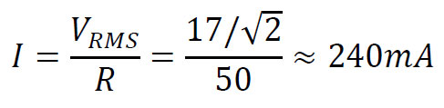
Now, say one uses the same 1nF load with lower frequencies (50kHz & 5kHz):
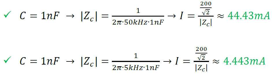
The maximum capacitance of a load that can be used without causing any damage to the amplifier, will depend on the frequency of the generated signal and each specific amplifier’s max current limitation.
Loads with inductive nature
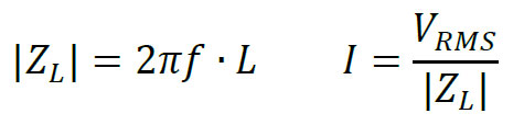
Inductive loads such as motors, transformers & other electro-mechanical actuators, will also change their impedance as frequency changes. The impedance of an inductive load will increase as frequency increases:
𝑍𝐿=𝑗∙2𝜋𝑓∙𝐿
Say one uses the 9260 amplifier with 1A current limitation and would like to generate a 34Vp-p sine wave at 1MHz on a purely inductive load:
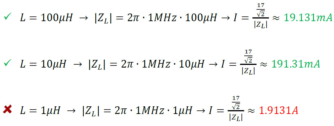
As can be seen above, 𝐿=1𝜇𝐻 load @ 1MHz will exceed the maximum current limit.
Now, say one uses the same 1𝜇𝐻 load with higher frequencies (10MHz & 20MHz):
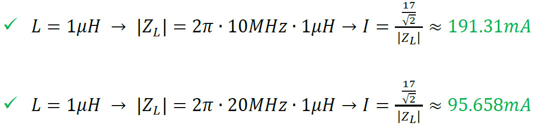
The minimum inductance of a load that can be used without any damage to your amplifier, will depend on the frequency of the generated signal and the amplifier’s max current limitation. Please notice low frequencies or DC offset are not allowed with inductive loads as applying DC voltage to inductive load will result in a short circuit.
For More Information
To learn more about Tabor’s solutions or to schedule a demo, please contact your local Tabor representative or email your request to [email protected]. More information can be found at our website at www.taborelec.com