Relevant Documents
 (199KB)
Background
I2C (or, Inter-Integrated Circuit) is a 2-wire communications bus used to provide connectivity between microchips on printed circuit boards and in embedded systems. Introduced in the 1980s by Phillips, I2C helps to maximize hardware efficiency and circuit simplicity, and is employed in a wide variety of electronic devices.
The I2C-bus requires only two bidirectional lines – a serial data line (SDA) and a serial clock line (SCL). Every device connected to the bus line has its own unique address and can act as either a receiver or transmitter. For the purposes of data transfer, devices can serve as masters or slaves:
- Master devices initiate data transfers on the bus and generate the clock signals to support the transfer.
- Slave devices are addressed by master devices
A sample I2C bus application appears in Figure 1 below.
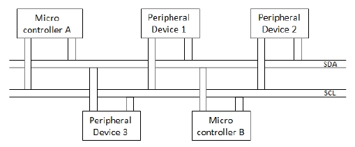
Figure 1: Sample I2C Bus Application
Requirement
An example of a data transfer over the I2C bus appears in Figure 2 below.
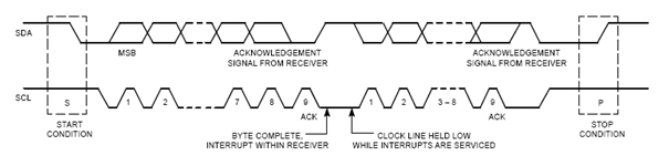
Figure 2: Sample I2C Data Transfer
In the example above, Micro-Controller A wants to write to a peripheral device. It issues a START, and sends the address of the device it wishes to address. The duration of this activity is 8 clock pulses. All the ICs on the bus compare the address transmitted with their own. If there is no match, they simply do nothing and wait until the bus is released by the STOP condition. If the address matches, the receiving device produces a response on the ACKNOWLEDGE signal issued by the Micro-Controller, and pulls the data line LOW. This is an indication to the Micro-Controller that there is a device with the required address on the bus. Now the Micro-Controller can start transmitting or receiving data. When all is done, the Micro-Controller issues a STOP condition, signaling that the bus has been released and that the IC's may expect another transmission to start any moment.
Simulating these types of signals is essential in testing the I2C interface of ICs, as well as their data transfer, signaling, and timing capabilities.
Solution
Tabor Electronics’ Wonder Wave family of Arbitrary Waveform Generators (AWGs) serves as an excellent platform for the testing of I2C components, offering resolutions of as low as 4 nanoseconds. Wonder Wave features 16-bit vertical resolution with 16 Vpp, allowing it to generate I2C signals, even at the 5.5 V level.
Wonder Wave’s advanced memory management capabilities support highly complex applications, offering storage of 10,000 repeatable waveform segments, with up to 4 million memory points.
Tabor’s ArbConnection control and waveform-editing software includes Pulse Composer – a powerful, graphically-based tool that is perfectly suited for the simulation of I2C signals.
For More Information
To learn more about Tabor’s solutions or to schedule a demo, please contact your local Tabor representative or email your request to [email protected]