- Signal Fidelity - Choose the correct sample rate vs waveform characteristics
Background
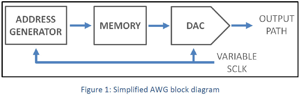
An Arbitrary Waveform Generator (AWG) allows users to create complicated signals using several built in features in a similar manner as with a Pulse/Function generator. It can also be used to create signals out of complex mathematical expressions or captured traces of real life signals. Such signals are stored in a dedicated arbitrary memory and are generated according to the specified memory address supplied by the address generator at a selected sampling clock rate. In order to increase playtime, advanced AWGs have sequencing abilities for creating playlists of waveforms stored in memory.
An arbitrary waveform generator has its limitations. For example, all AWGs are bandwidth limited, which is directly related to their specified maximum sampling rate. According to the Nyquist criteria, the sampling rate determines the maximum frequency range or modulation bandwidth which can be played by the AWG.
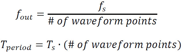
When using Tabor’s Signal Expert series of AWGs, the highest achievable sampling rate is 6Gs/s. Therefore, by following the equation above, the highest achieved frequency according to the Nyquist criteria will be:
Nyquist Criteria
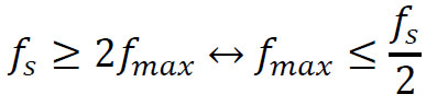
The Nyquist Sampling criteria state that the sampling rate of a signal must be at least twice the rate of its highest frequency component. Translated to the world of arbitrary waveform generators, in order to produce a signal of maximum frequency, 𝑓𝑚𝑎𝑥, the sampling rate, 𝑓𝑠, being used to generate the signal must be at least 2𝑓𝑚𝑎𝑥. Alternatively, the highest frequency signal a DAC with sampling frequency 𝑓𝑠 can generate is equal to half the sampling rate or 𝑓𝑠/2 (referred to as the first Nyquist zone).
Traditionally, AWGs work only in the first Nyquist zone (𝑁𝑍1≤𝑓𝑠 /2) as images in the higher Nyquist zones are suppressed, due to their components architectural limitations (BW).
But what if those images were not suppressed? This would mean that by applying a proper band pass filter (depending on the required bandwidth), it would be possible to generate signals well above the sampling rate of the AWG.
AWGs with higher order Nyquist zones
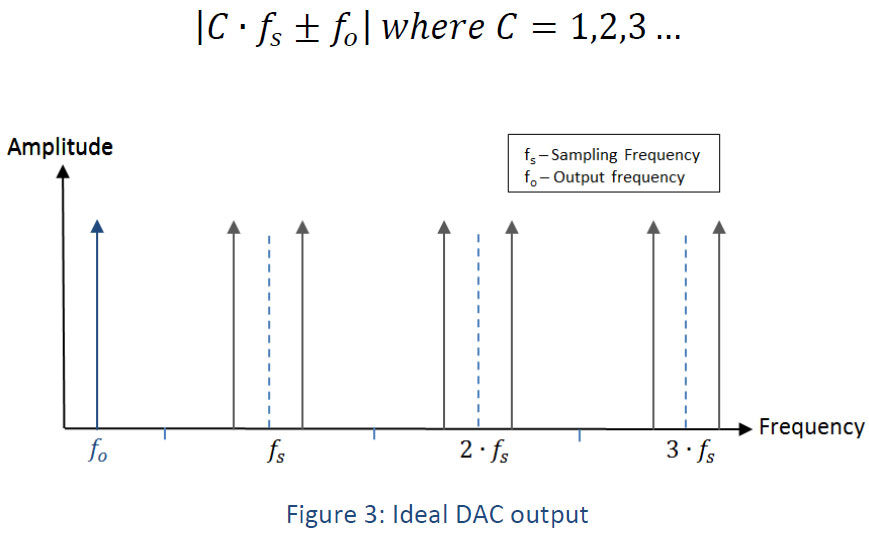
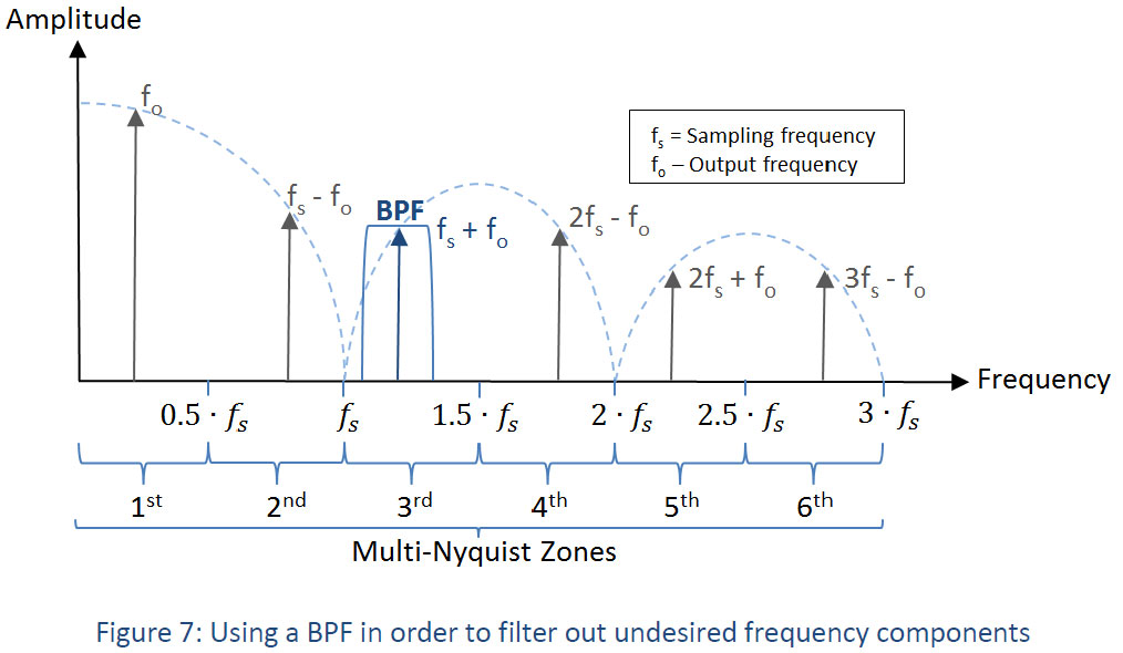
In the frequency domain, when generating a sinus waveform of frequency fo, it will appear as the fundamental spectral component at fo. However, there will be additional frequency products often referred to as images, at higher frequencies. These products are a function of the sampling rate and fo as can be seen in figure 1. These products are described by:
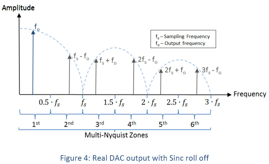
In real conventional DACs with standard non-return to zero, the output is a set of discrete voltage levels, where each level is held for a period of the sampling rate 𝑇𝑠. Therefore, the frequency response of such DAC is of 𝑠𝑖𝑛𝑐(𝑥)=sin(𝜋𝑥)/(𝜋𝑥). The amplitude of the images generated at higher frequencies than the first Nyquist zone is dependent on the roll off of sinc(x). It should be taken into account that as we go up in frequency, those images are attenuated as can be seen in figure 4:
Traditionally, DACs analog BW is not much higher than the BW of its first Nyquist zone causing the suppression of signals at higher Nyquist zones. The new DAC used in the Tabor Signal Expert series offers an exceptionally wide bandwidth reaching up to 7GHz and even beyond.
In addition, using different sampling modes, the DAC can optimize power performance according to the desired Nyquist zone, so that the higher frequency images are not suppressed.
With the Tabor Signal Expert series you get 4 selectable
sampling modes:
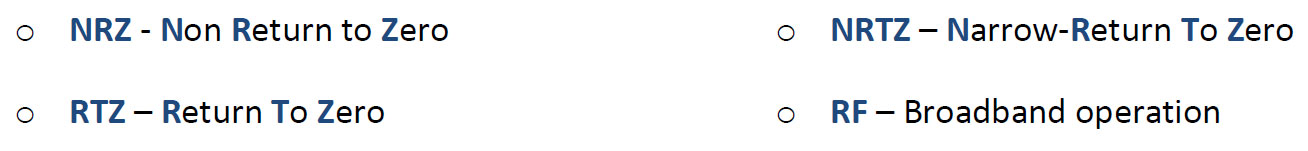
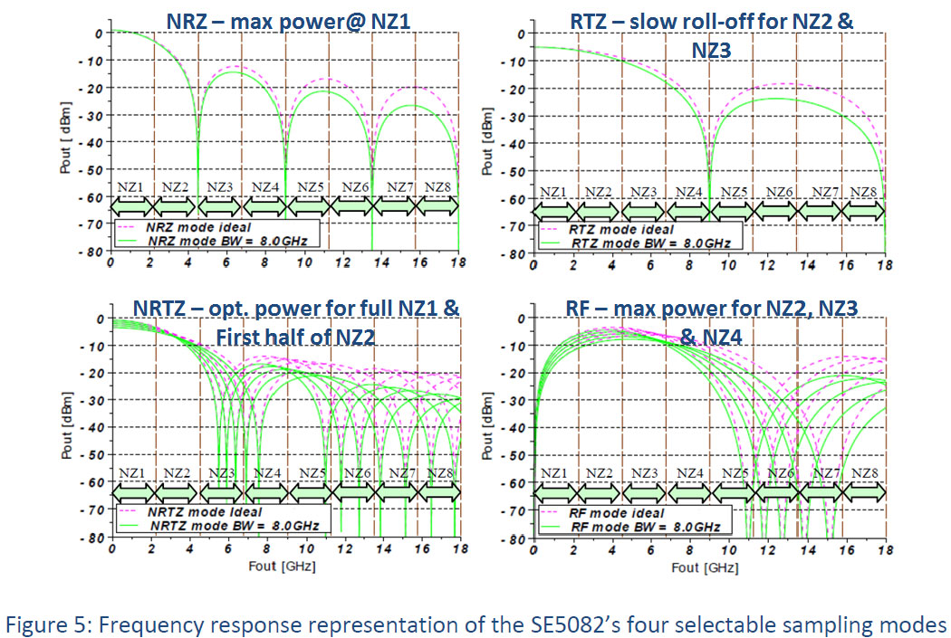
When using the proper sampling mode, images at higher Nyquist zones are passed through. Using a proper Bandpass filter, users can filter the unrequired frequency products and essentially generate signals at much higher frequencies.
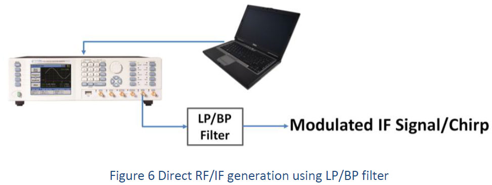
Here is how it is done using the SE5082:
The output frequency in the first Nyquist zone is determined by:
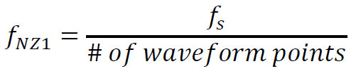
In order to generate a signal at a higher rate than the first Nyquist zone (≤0.5𝑓𝑠), one would have to determine what sampling rate & how many waveform points will be used:

For proper filtering to be achieved, one needs to move as far as possible from the sampling clock spurs by generating 𝑓𝑁𝑍1at relatively high frequency in order to generate enough spacing for successful filtering of other images and most importantly, the 𝐶∙𝑓𝑠 clock feedthrough.
Please keep in mind that as C gets bigger, most likely the power of the signal will get more attenuation by the sinc roll off.
Example: How to generate a 6GHz sine wave
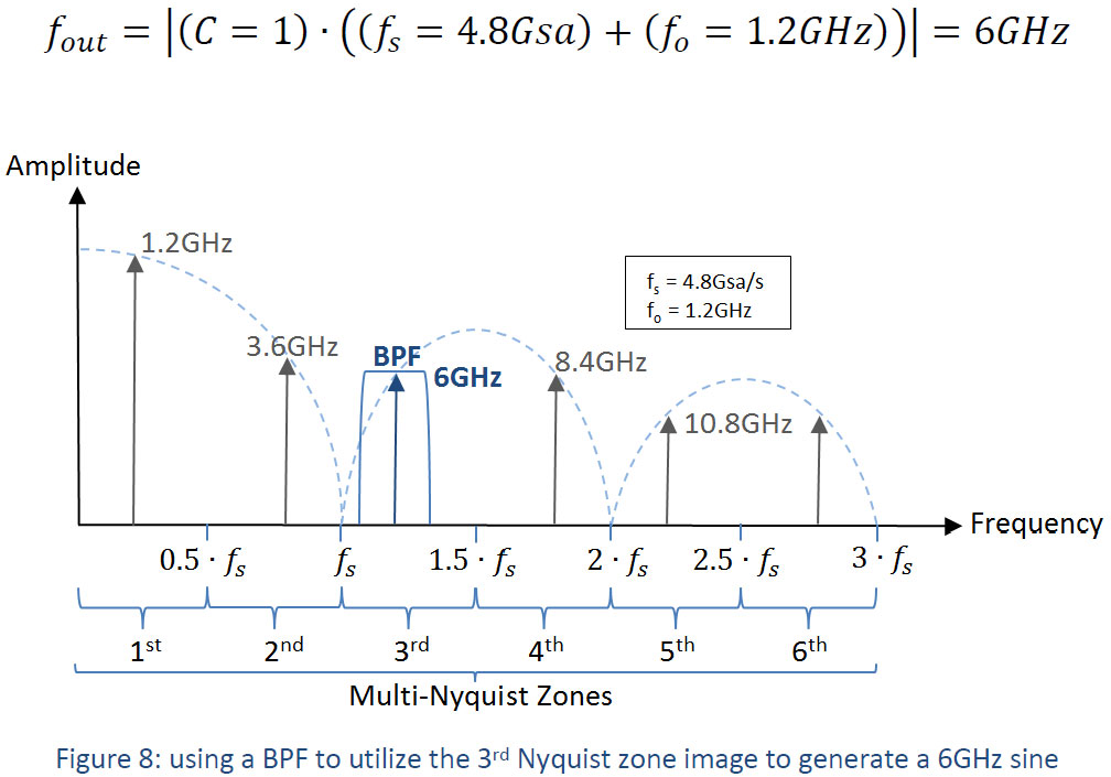
There is more than one option for generating a 6GHz signal, here is one utilizing the third Nyquist zone (NZ3):
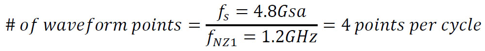
So all that is needed from now on is to understand how we could generate a 1.2GHz:
Here are the steps:
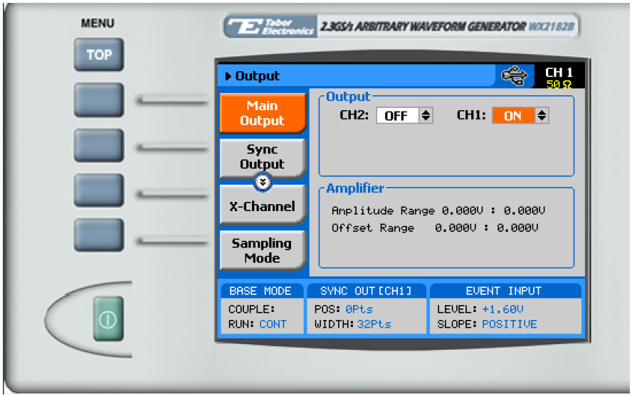
1. Turn the channel’s output ON:
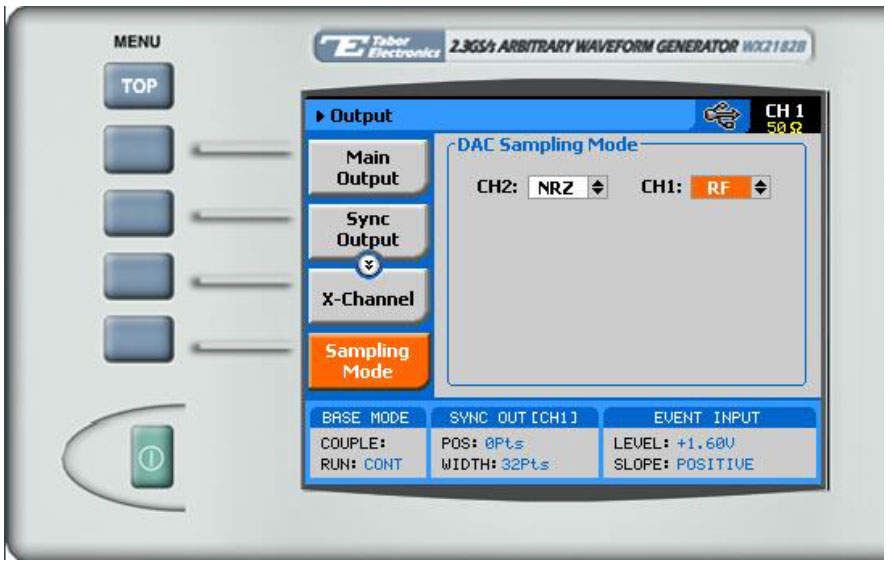
2. Change the sampling mode to be “RF”:
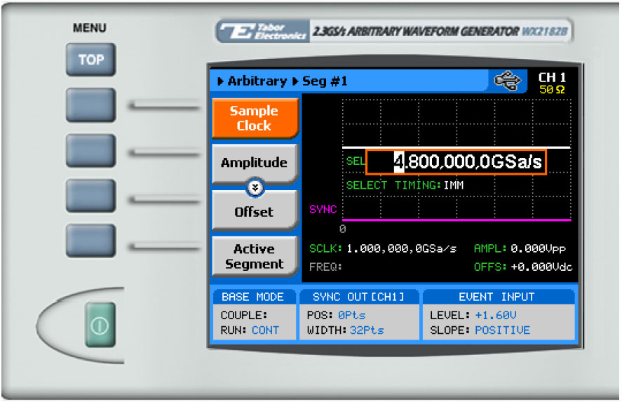
3. Move to arbitrary mode and change the Sample clock to 4.8Gsa/s:
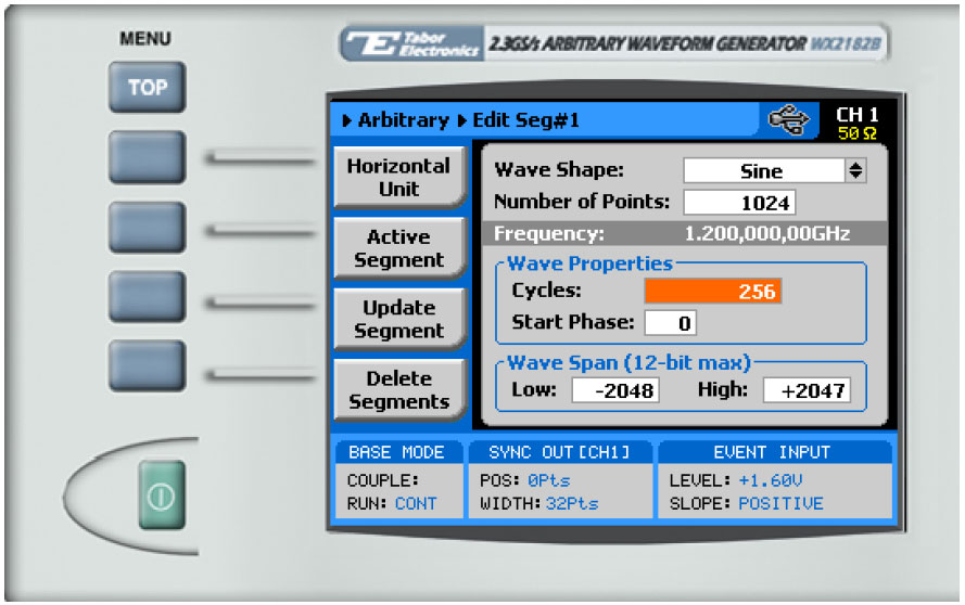
4. Open the Wave composer and create a sine wave with 4 points per cycle. Once finished, press ‘update segment’:
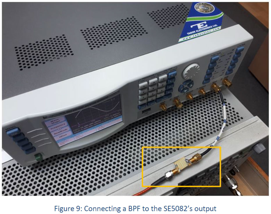
5. Apply a band pass filter to the AWG’s output in order to filter out all undesired frequency components. For this example we used a 5.75GHz to 6.25GHz BPF:
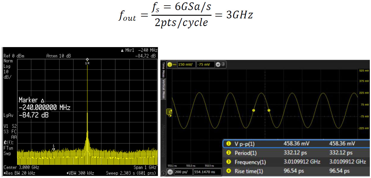
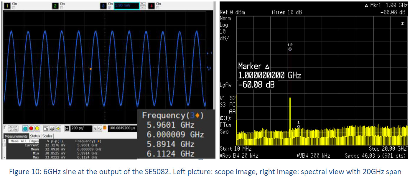
6. Here is what you should be able to capture on scope/spectrum analyzer:
To Conclude
The creation of additional image signals at the output of an UWB arbitrary waveform generator such as the SE5082 may be very useful for some applications. Such an AWG can be used to directly generate microwave frequencies without the use of external analog mixer and RF generator. However, attention must be given to the power and spectral purity of the required signal in higher Nyquist zones. As the images in higher Nyquist zones are attenuated, the power and dynamic range are reduced. In these cases external components such as amplifiers may help to achieve the power and spectral purity of the specific applications. Therefore, in many applications such as radar signals and complex digital modulation schemes, the required signals could be directly generated from the SE5082 output and save the end user the need for any additional equipment (VSGs, PSGs) or higher frequency AWGs.
Applications

For More Information
To learn more about Tabor’s solutions or to schedule a demo, please contact your local Tabor representative or email your request to [email protected]. More information can be found at our website at www.taborelec.com