1 - 802.11ad Introduction
The IEEE standard 802.11ad is a wideband millimeter wavelength addition to the 802.11 family of standards. It provides multi Gbps short range signals in the 57-71GHz band, supporting up to six 2.16GHz channels, each with 1760MHz bandwidth.
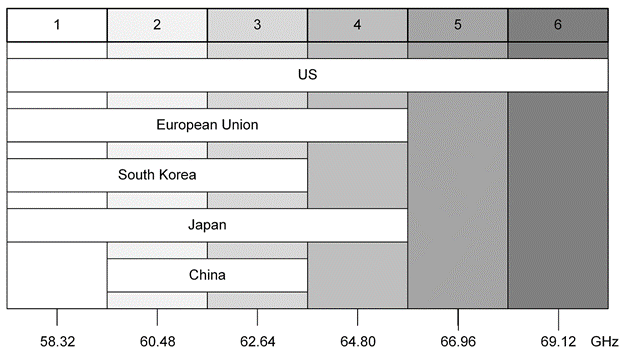
Figure 1.1: The 802.11ad standard defines up to 6 x 2.16GHz channels in the 55GHz-71GHz band. Available bandwidth also depends on the region.
This standard uses the 60GHz band and is available for use everywhere in the world.
A critical advantage of mm wavelength signals such as 802.11ad is the ability to design compact multi-element antenna arrays, which can be used for electronically controlled beam steering or beamforming, increasing the effective bit rate per user while minimizing the effects of multipath when using a single carrier modulation scheme. As with most mm wavelength systems though, its range is limited to effectively that of a single room due to high field attenuations and its inability to penetrate walls.
802.11ad uses two carrier schemes - OFDM (Orthogonal Frequency-Division Multiplexing), employing many orthogonally spaced narrow bandwidth carriers, or sub-carriers and Single Carrier (SC) using both narrow and wide bandwidth modulation.
Most of the modulation schemes of the 802.11 family use OFDM which has advantages in complex multi-path environments such as offices and homes. For example, with OFDM all the received power paths, no matter the DOA (Direction of Arrival) improves SNR (Signal-to-Noise Ratio) and reduces PER (Packet Error Ratio) thanks to the application of powerful error-correction coding. Additionally, OFDM is the perfect modulation scheme for the implementation of MIMO (Multiple-Input, Multiple-Output) wireless systems where multiple transmission and reception antennas work together to increase the channel capacity beyond the Shannon fundamental limits (which still applies for each individual antenna). However, there are several trade-offs: The power amplifier design becomes more complex as the Peak to Average Power Ratio increases with addition of more and more sub-carriers. Also, more sub-carriers require more processing capability - the sub-carrier creation method uses an IFFT and conversely the FFT at the receiver, combined with channel estimation and correction and MIMO operation. Finally long training sequences for each packet combined with a high usage of pilot carriers (for channel estimation) and guard intervals (cyclic prefix) devoted to the mitigation of multi-path, take a considerable portion of the channel capacity.
While high data rate, or wide bandwidth SC signals are susceptible to multipath interference, the amplifier, channel efficiency and processing requirements are lower. The use of beam forming can overcome many of the disadvantages of a single channel transmission making it a viable alternative to OFDM.
802.11ad transmission modes today use both use OFDM for high-throughput and SC modulation for lower data rates, the current revision states that the OFDM modulation modes are obsolete, and they may disappear in future revisions, so only the single-carrier modulation modes will be kept.

Figure 1.2: Summary of all the Modulation and Coding Schemes (MCS). Although, as usual in other 802.11 wireless networking standards, there are Single-Carrier Modulations and OFDM schemes, future releases of the standard may not support the OFDM schemes. The main advantage of OFDM, the mitigation of the effects of multi-path, may be overcome by the extensive using of beamforming techniques.
Transmissions are made of packets, and they share a common structure, no matter the modulation scheme being used:
- Preamble: Used for synchronization and channel estimation. It is made of two sections: the Short Training Field (STF) and the Channel Estimation (CE) sections.
- Header: Its contents depend on the MCS being used and it includes basic information for the packet as modulation mode, length of the payload, and some checksum protecting this content.
- Data: This is the part of the packet transporting the payload and its length is variable.
- TRN: This is an optional training sequence to help in the optimization of the beamforming functionality.
OFDM or SC modulation can be used in different sections of the packet. However, the specific modulation scheme depends on the section of the packet and the PHY being implemented. Preamble and headers use robust, fixed modulation schemes for a given PHY while the data section may vary depending on the target data throughput and the quality of the link.
There are three different PHYs defined in the standard:
- Control PHY: It carries service, signaling and control information. The complete packet uses the PI/2-BPSK single-carrier modulation. The PI/2-BPSK modulation scheme combines the high resilience to interference and noise of BPSK with a lower Peak-to-Average Power Ratio and avoids zero-crossing in the IQ plane. All the single-carrier modulated signals for 2.16GHz channels use a 1760MBaud signaling rate and a square root raised cosine baseband shaping filter with a 0.25 roll-off factor.
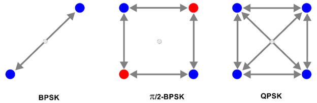
Figure 1.3: The PI/2-BPSK modulation scheme is extensively used by 802.11ad standard. In the left, the regular BPSK (1 bit per symbol) constellation diagram and the corresponding transitions are shown. In the right, the same information is shown for QPSK (2 bits per symbol). For both modulation schemes, the phase trajectory may travel close or over zero, leading to an instantaneous zero power transmission. The PI/2-BPSK rotates the regular BPSK constellation by 90 degrees for each symbol. The constellation looks like the QPSK one. However, just one bit is carried by one symbol. The advantage here is that zero crossings are avoided resulting in a better Peak to Average Power Ratio (PAPR) and a simple RF amplifier design.
2. Single Carrier PHY: There are two sub-types: Regular and Low-Power. In the regular mode, the preamble and header sections are the same as the ones in the Control PHY and they use PI/2-BPSK for modulation. However, the data section can support higher order modulation schemes to increase the channel capacity. PI/2-BPSK, PI/2-QPSK, PI/2-16QAM, and PI-2-64QAM are available. Modulation schemes applied to the data section of the packet in the Low Power version are limited to PI/2-BPSK and PI/2-QPSK, which have a higher mean power for a given peak-power than higher order modulations. The same considerations about signaling rate and baseband filtering made for Control PHY are valid for both SC-PHY sub-types. The PI/2 rotation of the constellations do not change statistically the QPSK, 16QAM, or 64QAM, just the one for BPSK, where it avoids zero crossings and improves PAPR. However, rotation is kept for the other modulation schemes as doing so it is not necessary to change the functionality of the constellation-rotation block when switching the modulation scheme within the same packet or between different packets.

Figure 1.4: In the right, a 2GHz BW single-carrier 802.11ad example (MCS 12.5). In the left, a 2GHz BW OFDM (MCS 13) signal is shown. Both signals are generated with the same peak power and the power advantage of the single-carrier modulation MCSs, with a lower PAPR, can be noticed.
3. OFDM PHY: For OFDM MCSs, the Preamble uses the same single-carrier modulation scheme that Control and Single Carrier Phys do. Some of the contents of the preamble change in order to inform the receiver that the rest of the packet is OFDM instead. The header section is already transmitted using OFDM with individual carriers being QPSK modulated. The data section can implement SQPSK, QPSK, 16QAM, and 64QAM. Notice that the modulations of the OFDM carriers are not rotated by PI-2 as there is not any advantage of doing it. SQPSK (Spread QPSK) and maps 2 bits to two different QPSK-modulated OFDM carriers, so data density is similar to BPSK. The OFDM parameters for 802.11a includes a IFFT sampling rate of 2.64GS/s, 512 samples IFFT, ¼ Cyclic Prefix, 355 active carriers (including 16 pilot, 3 DC, and 336 data carriers), with a total 1830.47MHz bandwidth, see above figure b).
The different modulation and coding schemes result in a variety of transmission rates and sensitivity requirements that provide sufficient flexibility for a large variety of wideband transmission services and network component complexity and cost.
While many IEEE 802.11 wireless network wideband standards strongly rely on the usage of MIMO or even massive MIMO techniques to increase channel capacity, the IEEE 802.11ad standard strategy is based on leveraging the extremely high carrier frequency to apply beamforming. Wireless routers can incorporate sophisticated electronically steerable small size phase array antennas. These antennas can direct multiple beams concurrently to different network devices. In this way, multipath distortions and interferences are minimized, available power at the receiver is optimized while carrier frequency can be reused. Special training sequences can be appended at the end of packets to help to optimize the antenna coefficients in real-time.
2 - 802.11ad Testing Strategies
Successful testing of 802.11ad wireless networks devices and components not only requires both stimuli (Signal Generation) and acquisition (Analysis) instrumentation at millimeter frequencies, but the testing instrumentation also needs to emulate a beamforming antenna array to compensate for the changing conditions of the transmission path.
For signal generation purposes, a suitable vector signal generator covering the 57-71GHz band with a modulation bandwidth of 2GHz or more, would be ideal for 802-11ad receiver testing. However, commercial offerings are rare and expensive. Alternatively, commercially available IQ modulators or up-conversion devices combined with an IF or IQ generator such as a high sample rate AWTs (Arbitrary Waveform Transceivers) offer a more cost-effective solution.
IQ baseband generation and acquisition is the most direct way to generate and receive an 802.11ad signal through an additional IQ modulator/demodulator reaching the 57-71GHz band. The target BW is around 2GHz, so I and Q baseband signals will require around 1GHz BW. Wideband IQ modulation can be difficult and the noise margin in the system strongly depends on the signal performance in terms of EVM, SNR, and phase noise (this is especially important for the OFDM PHY). As symbol rates and overall bandwidth grows, the fact that two physical waveforms must be generated and applied to the external IQ modulator makes channel-to-channel matching critical in terms of amplitude, frequency response, and skew. Additionally, IQ modulators can add their own linear and non-linear distortions such a quadrature error and imbalance, or AM/AM and AM/PM distortions while the LO (Local Oscillator) can introduce frequency errors and phase noise into the noise margin calculations.
A RF AWT can digitally generate and receive a perfectly balanced IQ modulated signal at an IF Frequency. Refer to figure 2b and 2c.
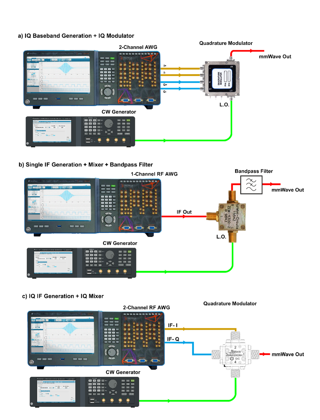
Figure 2.1: The three basic ways to generate a mm-Wave (millimeter wave) signal from a wideband AWG is shown here. At above figure a) the high sampling rate AWG generates two baseband (IQ) differential signals to feed an external IQ modulator. In b) a RF-oriented AWG generates a wideband IF signal connected to a mixer. A bandpass filter will be necessary to remove the unwanted image at the output of the mixer. Finally, at c) a dual-channel RF-oriented AWG generates concurrently two IF with the same modulation but with carriers with 90 degrees phase difference (quadrature conditions). The two IF signal are mixed using a specialized IQ mixer. The advantage of this method is that only one of the sidebands is preserved. Most designs use 90 degrees hybrids to obtain the two IF signals from one. However, directly generating the two IF signals with an AWG can simplify the process and obtain better results as signals can be pre-distorted to remove the spur images resulting from inaccuracies in the 90 degrees hybrid and/or the IQ mixer itself.
3 - Proteus Applied to 802.11ad
The above requirements for instrumentation for generating and acquiring 802.11ad signals can be easily fulfilled with the Proteus family of Arbitrary Waveform Transceivers (AWT). For baseband IQ 802.11ad acquisition and generation, the Proteus P2582M/B/D with the AWT option is the ideal solution for this application. It can be combined with a 60GHz wideband modulation/demodulation module or system such as the Analog Devices EK1HMC6350 Evaluation Kit for a completely functional TX/RX solution.
The figure below shows the block diagram of Proteus AWT and Figure 3.2 shows the block diagram of the complete solution based in the Analog Devices Evaluation Kit.
In this solution note, the signal flow from waveform calculation until waveform analysis will be shown.
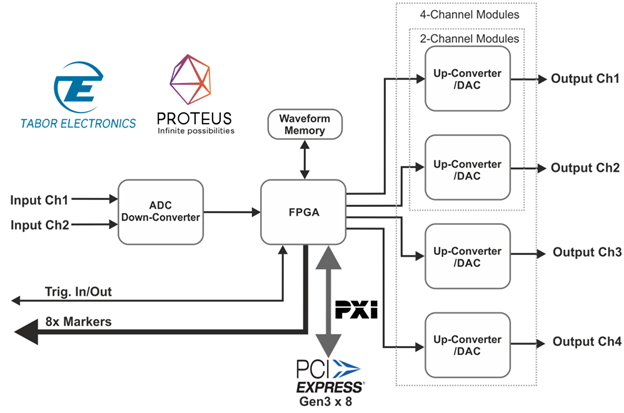
Figure 3.1: Simplified block diagram of the Proteus Arbitrary Waveform Transceiver (AWT). For PXI modules, up to 4 AWG channel, 2 Digitizer channels and 8 digital outputs can be fit in a 3-slot unit. The FPGA can perform real-time digital signal processing or support the implementation of user-defined functionality. Waveform memory is huge (up to 16 GSamples) and segmentable so extremely long signals can be generated even for such a wideband standard such as the 802.11ad.

Figure 3.2: Example implementation of a 802.11ad TX/RX test system using the Proteus P2582M (2 AWG channels @ 2.5GS/s, 2 ADC channels at 2.7GS/s) and the Analog Devices EK1HMC6350 evaluation board.
The basic characteristics of the P2582 AWT are the following:
- 2 AWG channels with 16-bit resolution with sample rates up to 2.5GS/s.
- 2 ADC channels with 12-bit resolution with sample rates up to 2.7GS/s
- Extremely high analog BW for generation (56ps rise-time) and acquisition (>8GHz analog BW) so multiple Nyquist Zones can be used
- Up to 8GSamples of internal, waveform memory for generation (including advanced sequencing) and acquisition
- Extensive internal and external triggering capabilities for both the generation and acquisition blocks
- Real-time standard and user-defined real-time signal processing through the bult-in Xilinx Virtex FPGA
The implementation of any receiver test starts with the creation of the waveforms that meet the test goals. AWGs are general-purpose instruments, and they can generate virtually any waveform if the waveform memory and sample rate/analog BW are sufficient. 802.11ad signals can consist in a single, short RF packet, or they may be made of multiple packets following a defined sequence. MATLAB/Simulink from MathWorks with the WLAN Toolbox, supports the existing 802.11 standards including the more traditional a/b/g/n standards and the higher speed, newer ones such as the ax and ad standards. Waveforms can be created by calling a function or created using the interactive GUI.
The figure below shows an example of 802.11ad waveform creation. It is a 2GHz BW IQ OFDM waveform for MCS #13. The sampling rate for the output waveform is either the natural sampling rate for the IFFT used in the OFDM MCSs or a multiple of the symbol rate for single-carrier modulation MCSs. In the example shown, the sample rate for the calculated baseband IQ waveforms is 2.64GS/s. Actual modulation bandwidth, though, is slightly higher than 2GHz as the outermost carriers are not used.
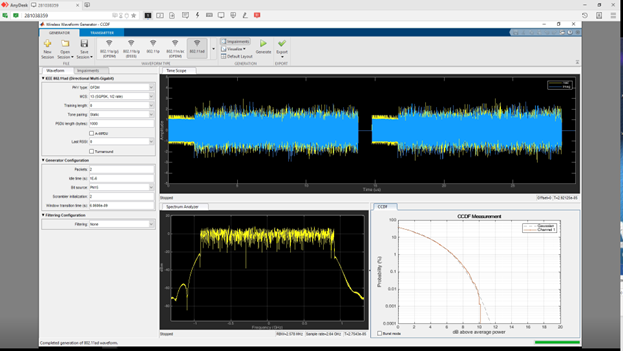
Figure 3.3: The Wi-Fi Toolbox for MATLAB can be used to create and analyze 802.11ad signals among many other standards. Here, MCS 13 OFDM signals made of two packets are created. The created signals can be analyzed from the supplied tools or exported as .mat files or MATLAB code to be integrated in any test application.
A general issue affecting waveforms coming from external sources (math applications, acquired by external instrumentation) is that the native sampling rate for the waveforms may not be convenient for the AWG requirements. In this particular case, the native sampling rate (2.64GS/s) is higher than the one supported by the AWG (2.5GS/s). The available modulation BW for this AWG is around 2.45GHz so the 2.1GHz BW OFDM signal can be effectively generated by the instrument. However, the sampling rate for the waveform must be adapted through a process called resampling. Resampling can increase (up-sampling) or reduce (down-sampling) the original sampling rate.
When resampling we need to avoid losing information or distorting the signal in the process. In this example, sampling rate must be changed from 2.64GS/s down to 2.5GS/s while preserving all the relevant information and accuracy in the time and frequency domains. Figure 3.4 shows the original and resampled waveforms in the frequency domain. Resampling also changes the waveform length as the time window implemented by the resampled waveform must be the same as the original one.

Figure 3.4: Often, test waveforms are not calculated at the final sampling rate for the target AWG. Therefore, resampling is necessary. Two cases of resampling are shown. In the left the original 2.64GS/s sampled signal (in blue) is resampled to 2.5GS/s (in red). In the right, the same signal is resampled at 2.25GS/s (so it can be played back at 9GS/s with 4X interpolation) Proper resampling must preserve all the significant information for the original signal. Here, resampling effects only show up in the skirts of the OFDM modulation at very low levels.
Once the complex waveforms have been calculated (two real waveforms, I and Q), they must be properly scaled for generation. The common practice for two-channel IQ baseband generation is setting up the same full-scale amplitude for both channels to improve channel-matching. The best possible SNR will use the full DAC range for both waveforms. However, as peak-to peak amplitudes for the I and Q components will be close but not equal, it is necessary to normalize both signals together so the original relative amplitude at the output of both signals is preserved when the output full scale amplitude is the same. Once the signals are normalized to some arbitrary limits (i.e. the -1.0/1.0 range), the next step is quantization to the 16-bit unsigned integer native binary format of the AWG.
The signal can then be downloaded to a memory segment in the AWG. In a perfect world, both channels would generate those signals in perfect synchrony and delivered to the external modulator in the same way. However, there may be time skews within the AWG, in the cabling or even within the IQ modulator. Skews can be corrected without recalculating the IQ waveforms through the independent delay control for each channel. In the Proteus AWT product, hardware-based skew adjustment can be performed with 5ps resolution.
Capturing the baseband signals from the IQ demodulator is very close to generating the signals with the signal flowing in the opposite direction. Using Proteus, both baseband signals can be captured synchronously at sample rates up to 2.7GS/s. In this case, resampling will not be necessary as the 2.64GS/s sampling rate is within the range of the ADCs in the Proteus platform. The resulting IQ signals must be supplied to some analysis SW to obtain the desired test results. This may be a quite complex process, especially when some OTA (Over-The-Air) test is performed. The received signals may suffer of all kinds of multi-path distortion, doppler shifts, quadrature error or imbalance from the demodulator, frequency error from unaligned LO noise, etc. Fortunately, the MATLAB WLAN Toolbox also implements all the functionalities of a complete receiver and the different steps in the demodulation chain can be activated or not depending on the functionality already supplied by the external demodulator. In the figure below, transmitted and received waveforms are shown in both the time and frequency domain.
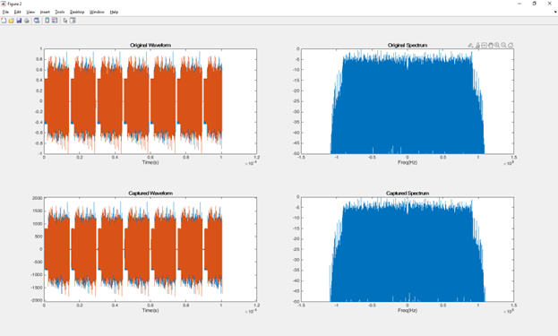
Figure 3.5: At the top, the original MCS 13 OFDM I/Q (blue/red) signals is shown as calculated in the time and frequency domains. At the bottom, the same signals are shown after being generated by two Proteus AWG channels at 2.5GS/s and captured by the two ADC channels at the same sampling rate. As it can be seen, the integrity of the signals in both domains are preserved.
The Proteus AWT is not limited to 2.5GS/s performance. The P9484M/B/D AWT product can go one step further and it supports up to 9GS/s in direct non-interpolated mode with 8-bit sample resolution and in interpolated mode with 16-bit sample resolution. Using the direct 9GS/s capability can be used to shift the image in the second Nyquist Zone far beyond of the image corresponding to the 2.5GS/s.
For a 2.2GHz BW 802.11ad, the 2.5GS/s AWG would show an image for each baseband component in the second NZ starting at 1.4GHz. This gives around 300MHz for the roll-off of a LPF (Low Pass Filter) to remove the unwanted images. Using 2x interpolator and 5GS/s DAC sampling rate, the first image will start at 3.9GHz, so now the available band for the LPF roll-off will be 2.8GHz. Using the 4X interpolator and 9GS/s DAC rate (reducing the baseband sampling rate to 2.25GHz) would move the beginning of the unwanted signal to an outstanding 7.9GHz. In either case, implementing a good enough LPF will be much simpler and cheaper, and, in some cases, the filter can be removed as images may fall beyond the modulation bandwidth of the IQ modulator, see below figure. Additionally, using interpolation is equivalent to increasing the resolution of the DAC by half a bit every time sampling rate is doubled.

Figure 3.6: Using the P9484, with the capability of real-time oversampling 802.11ad signals up to 9GS/s, the unwanted images located in upper order Nyquist Zones can be removed. In the right, the I signal is generated at 2.5GS/s, so the Nyquist frequency is 2.5GHz. The zero of the zeroth-order hold response at 2.5GHz can be observed. In the right, the same waveform is generated at 4x real-time oversampling. Images are removed so low-pass filtering to remove the upper images is no longer necessary.
4 - Beyond Baseband Generation and Acquisition
The above methodology will generate and capture 802.11ad signals in the 60GHz band. However, the Proteus offers additional ways to perform the capture and generation of such signals. Using IQ modulators with such a wide modulation bandwidth is challenging, basically due to the difficulty of matching the I and Q signal paths and the phase alignment of the quadrature modulator itself. Any difference or misalignment will result in an image in the mirror frequency in the opposite sideband for any frequency component causing the signal to interfere with itself reducing the noise margin.
Generating the 802.11 ad signal as an IF signal and using a mixer and LO is an excellent alternative methodology, Figure 2.1 5b). The advantage of this method is that the implementation of an IQ modulator at a lower carrier frequency is simpler, more accurate, and cheaper than doing it directly at the 60GHz band. In particular, using a lower IF opens the door to generate the IF signal directly with a suitable AWG. Generating the modulated signal with an AWG removes all the issues related with IQ imbalance, phase error, DC offset, I/Q frequency response matching and I/Q skew as modulation is made mathematically rather than by physical components.
The Proteus P9484M/B/D is the ideal platform to generate wideband modulated RF signals, directly up to 13GHz, or as an IF to feed a mixer for higher frequencies such as the 60GHz band. What makes Proteus an excellent tool is that each channel incorporates two DUC (Digital Up-Converter, implemented using a real-time numerical IQ modulator) attached to an independent NCO (a numerically controlled oscillator acting as an LO) meaning complex (IQ) samples can be stored in the memory at a lower sampling rate as interleaved I/Q pairs, interpolated to the final DAC sample rate and converted into the RF signal using the built-in DUC in real-time.

Figure 4.1: The P948x series incorporates two DUCs (a combination of interpolator, IQ modulator, and an independent Numerical oscillator) per channel. Up to 2.5GHz modulation bandwidths are supported (half channel mode) so 802.11ad IF signals for any MCS supported by the standard can be generated. IF frequency and spectrum reversion can be performed without downloading new waveform data. Channel-to channel carrier phase and amplitude for each IF signal can be controlled so creating beamforming scenarios is very straight forward.
This results in a higher quality signal where the carrier frequency can be changed instantaneously on the fly just by changing the contents of the frequency control register without having to recalculate the baseband waveforms already in the generation memory. The P9484 can generate four RF modulated signals at the same time with modulation bandwidths up to 1.25GHz. However, the modulation circuits from two channels can be combined to double the available modulation BW, to 2.5GHz modulation BW. This mode can be used to support all the 802.11ad MCSs. Using the 2x interpolation factor and a 5GS/s DAC sample rate, it is possible to set an IF in the 750MHz to 1.750GHz band approximately. Using the 4x interpolation factor and the 9GS/s DAC sample rate, the IF frequency range is extended to 3.750GHz. The upper or the lower sideband after the mixer can be selected just by controlling the DUC itself without the need to reverse the I or the Q components.

Figure 4.2: Two IF signals at 1.5GHz are generated here. The one in the left is a single carrier signal (MCS 12.5) and the one in the right is an OFDM signal (MCS 13). The slant of the spectrums is caused by the roll-off of the oscilloscope used to capture the signals.
A variation of the mixer method is to use an IQ mixer, Figure 2.1 5c). With IQ mixers, two IF signals modulated by the same IQ signals are fed to a dual mixer arranged as an IQ modulator. Magic happens when the carriers for each IF signal are 90 degrees apart. When this happens and depending on the sign of the 90 degrees difference in the IF carriers, one of sidebands at the output of both mixers are added while the other sidebands are subtracted. This increases the output signal power and makes the design of the system easier. The standard method of generating two IF signals is to generate a single IF signal and then apply a 90-degree offset. Theoretically this approach works, but for wideband signals some new impairments can be generated by the 90-degrees offset and its connection to the IQ mixer. Any imbalance or phase error will show up as a distorted signal, plus a residual unwanted sideband. The Proteus P9484M/B/D can improve the usability and quality of an implementation based in IQ mixers, by using two channels to generate the two IF signals using the same modulation data and carrier frequency while the 90-degrees phase offset can be obtained by setting up the relative phases of the NCOs applied to each DUC. This results in distortion caused by the 90 degrees hybrid being removed and the differential corrections can be applied to the I and Q part of the IF signal so flatness and image rejection can be optimized.
Using mixers is also a good alternative in the receiver side, as it results in a single modulated IF signal that could be acquired with a single channel digitizer. AS we discussed earlier the Proteus digitizer, when both input channels are used, is limited to 2.7GS/s sample rate so the maximum modulation BW is 1.3GHz, which is not enough for all the 802.11ad signals. However, both ADC channels can be interleaved, effectively doubling the sample rate to 5.4GS/s and increasing the BW to more than 2.5GHz.
Which is more than enough to acquire any of the 802.11ad signals. Also, multiple Nyquist Zones can be used to create IF frequency bands up to 8.5GHz.
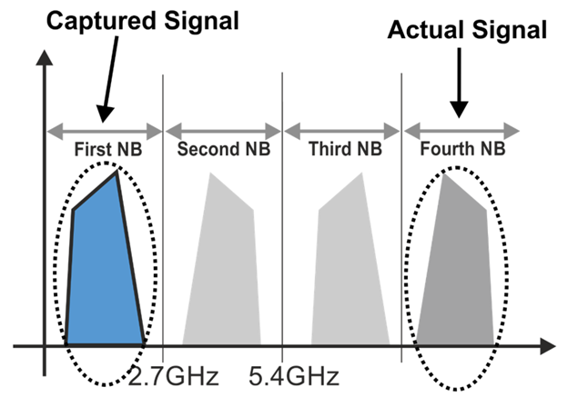
Figure 4.3: The digitizer in the Proteus platform is designed to be used with signals from DC up to 8.5GHz. It supports modulation BW up to 2.7GHz so it can capture 802.11ad IF signals with one single channel. To successfully capture a signal, it must fit any of the available Nyquist Zones. The boundaries of the Nyquist Zones can be controlled by setting up the adequate sampling rate for the ADC.
As described in the first section of this solution note, one of the foundations of the 802.11ad is beamforming. Beamforming requires transmitting the same modulated signal through multiple antennas controlling or weighting the delay and amplitude, forming a beam pointing towards the intended receiver. For narrowband signals, a beam can be controlled by changing the amplitude and the carrier phase for each antenna. Depending on configuration and model a Proteus AWG can have up to 40 channels per 19” chassis, see figure below. As delay, amplitude (by setting the full-scale level), phase (by rotating the IQ signals), and delay for each IQ channel pair can be controlled for each IQ modulator associated to each antenna, a single LO with constant phase can be used for all the modulators. For the mixer-based method, the phase of each IF carrier can be also controlled, the same phase and amplitude control strategy applies.

Figure 4.4: Generating beamforming scenarios is greatly simplified using the Proteus modular architecture where tens of IF or baseband signals can be generated and acquired while the phase for the carrier of each antenna as well as the amplitude and the IQ controlled skew can be fully controlled from the Proteus hardware once the external modulators/mixers/cabling has been characterized and corrected.
5 - Conclusion
The Tabor Proteus series of Arbitrary Waveform Transceivers can generate and acquire ultra-wideband wireless signals in the mm-Wave region. It combines high sampling rates with very high bandwidth input and output stages, with tight synchronization across multiple channels.
Generation and analysis can be performed using IQ baseband signals with I and Q on each generator or acquisition channel, or fully modulated IF signals using the built-in DUC/DDC functions with more than 2GHz of modulation/analysis BW.
Proteus has a scalable architecture capable of ten, even hundreds, of synchronized and coherent output and input channels, allowing for the creation of test systems supporting beamforming and/or MIMO.
6 - Arbitrary Waveform Generators - Proteus Series
The new Proteus Arbitrary Waveform Generator is ideal for next generation communications applications. Built on the latest RF DAC and RF ADC technology, the series has sample rates up to 9GS/s and multiple Nyquist zone frequency range capability in excess of 10GHz. It’s an innovative task oriented programming environment, and user programmable FPGA. When used in combination with its optional RF Digitizer it gives you the ability to change waveforms in real-time - ideal for improving the coherence time of a Qubit, characterizing an RF amplifier, or responding to an EW threat.
Arbitrary Waveform Generator - Multiple form factors to match your application
The Proteus series comes in a PXIe module, desktop, or benchtop platform. With the PXIe form factor, you get all the advantages of PCIe based high speed data transfer, waveform streaming, and large channel counts in a plug-and-play platform. The Benchtop has an easy-to-use front panel with a large screen and keyboard. The Desktop offers all the features of the Benchtop, at a lower price point – all you do is supply your own screen and keyboard.
Upgrade to Transceiver
The Proteus series can be upgraded to an Arbitrary Waveform Transceiver. The system integrates the ability to transmit, receive and perform digital signal processing all in a single instrument.
 Proteus Infinite possibilities (5085KB)