We have learned so far that the ENOB summarizes the impact of multiple linear and non-linear distortions and noise sources with respect to the quality of the output signal of an AWG. However, it does not provide all the information required to assess the performance of an AWG for different types of signal conditions. For example, if you are generating a signal and the most important factor is timing, i.e. the position of its rising or falling edges, such as those used in high-speed digital or radar applications; the vertical resolution is not as important as the position of the edges on the horizontal axis. Using the case of high-speed digital, an AWG can generate a multi-level PAM (Pulse-Amplitude Modulation) signal by defining the level corresponding to each successive symbol. If the symbol rate is a multiple of the sampling rate, then edges can be positioned in the right places without any added jitter (other than the sampling clock jitter itself). If this is not feasible, or the application requires a continuous edge positioning (i.e. to generate a controlled amount of jitter), the ideal transition instant would be located anywhere between two consecutive samples, so the resulting signal will incorporate an additional jitter component with a peak-to-peak amplitude equal to the sampling period of the AWG.
However, an accurate edge position can be achieved by controlling the amplitude of the samples in the transition between consecutive symbols. Maximum control on edge position is accomplished when the transition time for any edge is at least twice the sampling period, so two samples are used to implement the edge, see Figure 2.1: The amplitude of those two samples will define the precise location of the corresponding threshold crossing event. In this case, timing resolution is influenced by the vertical accuracy (and resolution) of the samples. In practice, it may be small compared to the intrinsic jitter of the generator caused by the sampling clock jitter and additive noise. Consider a 12-bit DAC @ 4GSa/s, this can generate a 4Gbps serial binary signal, however, a 250pspp jitter is added in the process. Alternatively, an 8-bit, 8GSa/s DAC can produce the same signal, but the jitter is now reduced to less than 1ps, refer to Figure 2.2: The difference between the sampled signal and the ideal signal is an error signal, which can be considered as a reduction in the effective number of bits. In this example, the accuracy of the 8GS/s, 8-bit DAC will be much better than the one corresponding to the 4GHz, 12-bit DAC. In other words, for many signals, sampling rate and/or analog bandwidth may be more critical than the ENoB specification for a particular DAC.
Another source of confusion is the impact of vertical resolution and ENoB in the quality and accuracy of narrowband signals, such as those used in wireless, mobile telephony, and broadcast networks. The direct translation of equation (5) to the actual SFDR or SNR of a narrowband signal generated by an AWG at first glance may make the choice of an AWG unsuitable. First, it is important to remember that quantization noise is spread all over the Nyquist band, so the most important number is noise power density (NPD). NPD depends roughly on the ENoB specification and the sampling rate. The higher the sampling rate, the lower NPD level for the same ENoB specifications. SNR for a narrowband signal is defined by the noise within the channel as the noise outside the channel can either be filtered out at the output of the generator or at the input of the DUT. However, ENoB does not provide a complete description of the different contributors to the degradation of the vertical accuracy of a DAC. While quantization noise is spread rather uniformly over the full Nyquist band, the nonlinear behavior of the DAC or the output stage results in harmonics and Third Order IMD (Inter-Modulation Distortion). Harmonics and Intermodulation can appear in or out of the band of interest. A very-linear DAC with a lower ENoB specification may be much better than a not-so-linear DAC with a higher ENoB number as the latter will concentrate the power of the error signal in the proximity of the signal being generated, see Figure 2.3. If a signal is generated in the center region of the Nyquist band, all the harmonics created by the non-linear behavior of the generator will show up (folded down) in the same band as the desired signal, thus leading to interference and ACPR degradation. Again, a lower ENoB specification may be much less important than the overall linearity of the DAC and the output stage.
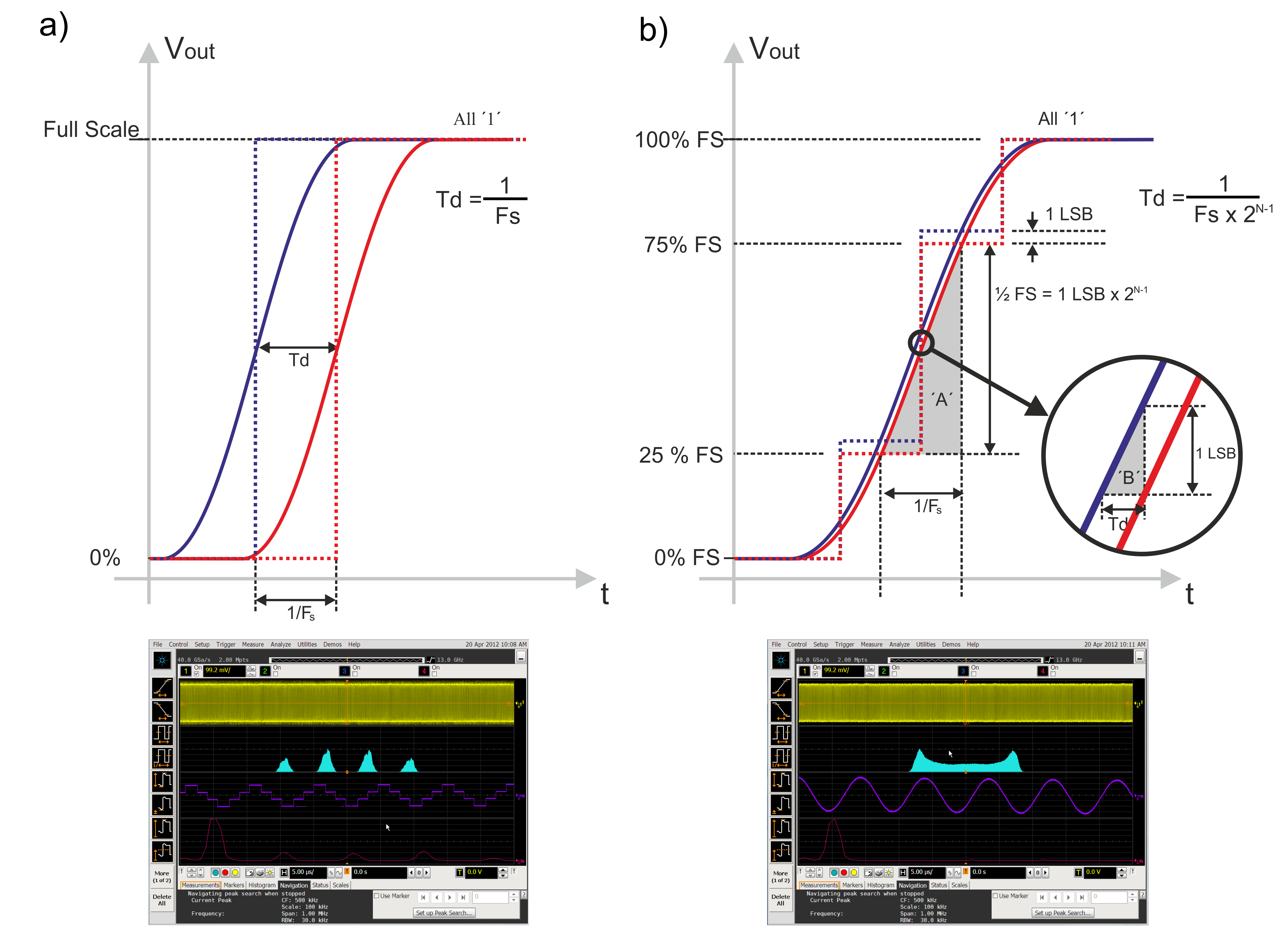
Figure 2.1: In some areas, timing information may be more important than the instantaneous amplitude of the waveform. The capability of an AWG to position an edge depends on the number of samples used to implement that edge. In a) the edge is produced by simply switching the amplitude from minimum to maximum value in one sampling time (top). This will produce a very fast edge, but the granularity of the edge position will be 1/Fs. If the application requires the generation of a sinusoidal jitter profile, an analysis of the jitter behavior will show the quantization of the instantaneous jitter to multiples of 1/Fs (bottom). If two or more samples are used in the transitions, as shown in b), edge position granularity will be greatly improved, even for low resolution DACs. In the bottom jitter analysis, the same amount of sinusoidal jitter is produced without any noticeable quantization.
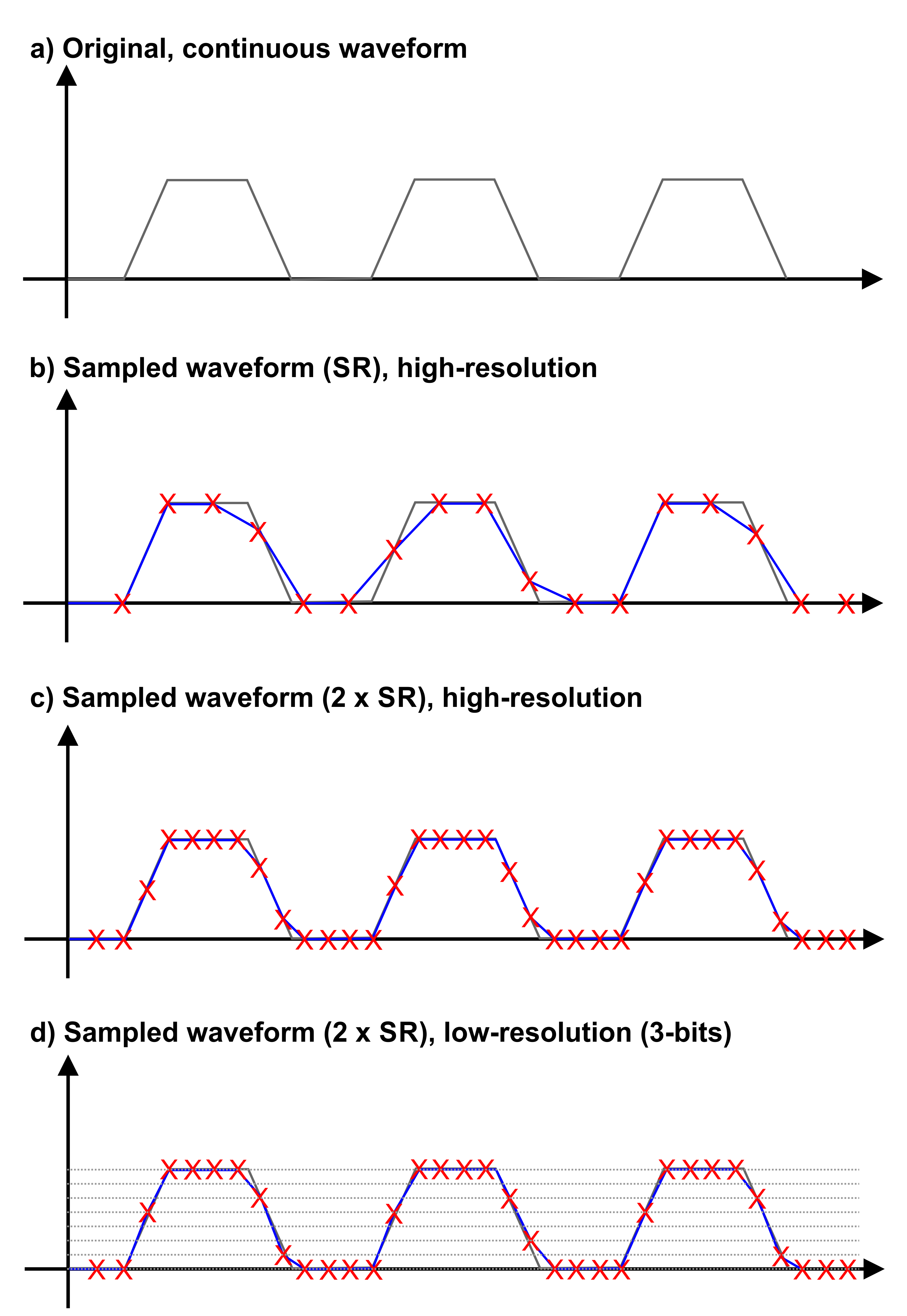
Figure 2.2: Increasing the ENoB specification is not always useful to improve signal generation accuracy. Often, the sample rate and bandwidth may be more critical to the application. In this example, a clock signal (not a submultiple of the sampling rate) is generated (a). The sampled version of this signal is shown in b). The differences with the original waveform are very visible and affect to the timing location of some of the edges. In c) the same signal is generated at twice the sampling rate. As the sampling rate is higher and the 2-sample time per edge criteria is met, the resulting signal is much close to the original one while the 50% crossings occur exactly at the same time as the original signal. Finally, in d) a low-resolution (3-bit) quantized version of the previous waveform is shown. Even with such a low resolution (just 8 quantization levels), signal fidelity and timing consistency is much better than the ones corresponding to the high-resolution, half sample rate version of it.
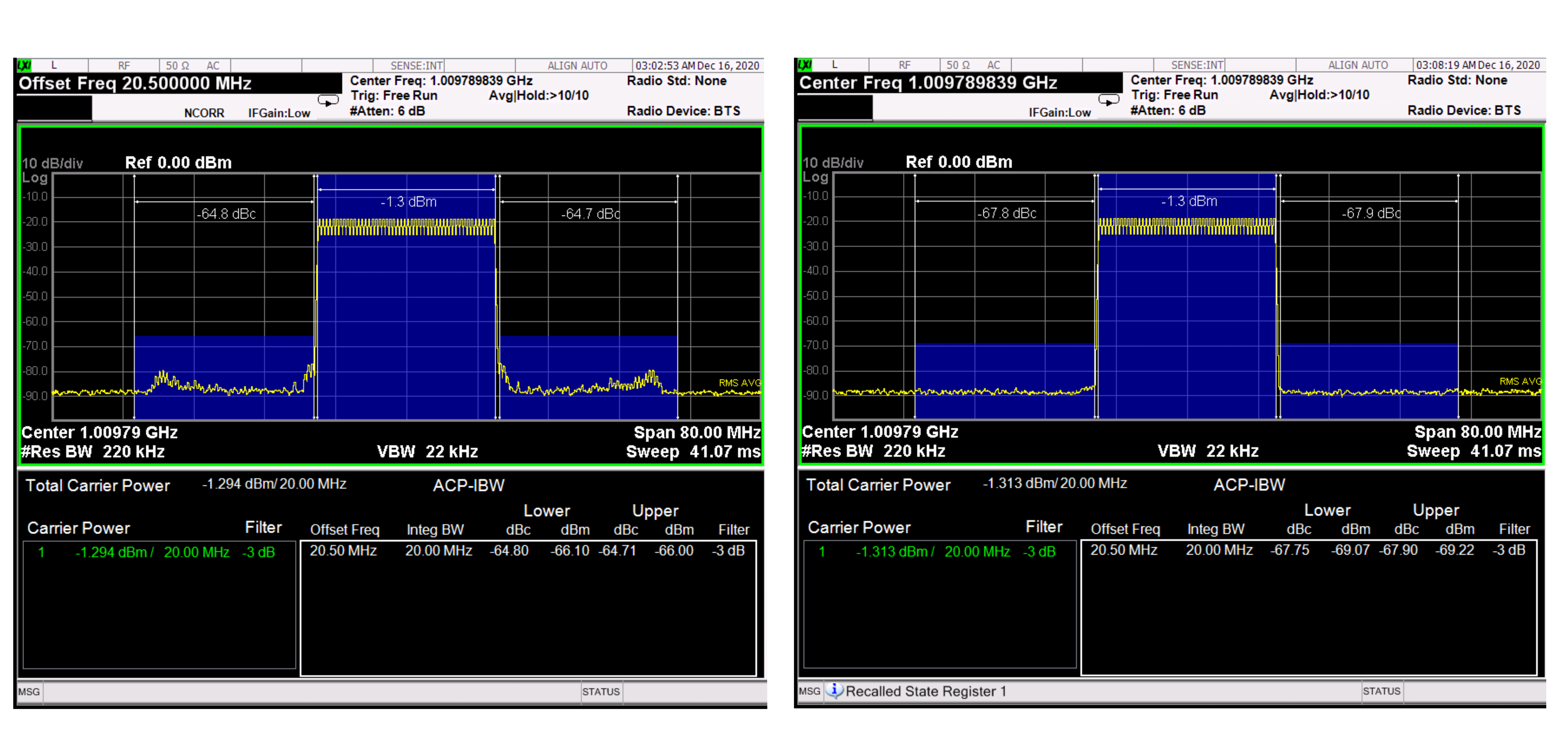
Figure 2.3 ENoB groups multiple sources of error. Narrowband signals may be more influenced by some components. On the right, a 20MHz bandwidth signal @ 1GHz is measured using two AWGs with similar ENoB specifications. However, the signal is generated using two different output stages. In the left, where an amplified output stage is used, intermodulation products and skirts are visible in the adjacent channels. On the right hand side, using a direct DAC connection, these unwanted components are buried in the background noise. As a result, the ACPR (Adjacent Power Ratio) improves by more than 3dB.
Avoiding the central region of the Nyquist band is a good practice but it is not always possible, especially for signals with very high modulation bandwidths. Finally, in some applications, it is possible to improve the SNR and SFDR of the signal by applying some advanced correction techniques. These are based on the “noise shaping” principle. (A technique used in Hi-Fi audio.) We know that quantization noise will always be generated by a digital-to-analog converter, but the signal could be created in such a way, so the noise is not uniformly distributed all over the Nyquist band and removed from some band of interest. But remember the noise out of this band will increase accordingly. Sigma-Delta modulation is a technique that can be applied after a careful characterization of the DAC. However, characterizing the DACs to the level of accuracy required by the signal-delta technique may be very difficult, especially with high speed AWGs. Nulling-Tones, refer to Figure 2.4: is a different technique where IMD products can be removed within the band (i.e. for a notch in a multi-tone signal) or in the adjacent channels (i.e. for a more accurate ACPR measurement of an RF amplifier). The nulling-tones technique is applied by calculating tones that interfere destructively with the undesired IMD products. An iterative calibration process using an external Spectrum Analyzer can result in an excellent improvement of the SFDR that would be impossible to accomplish even with the highest performance DACs.
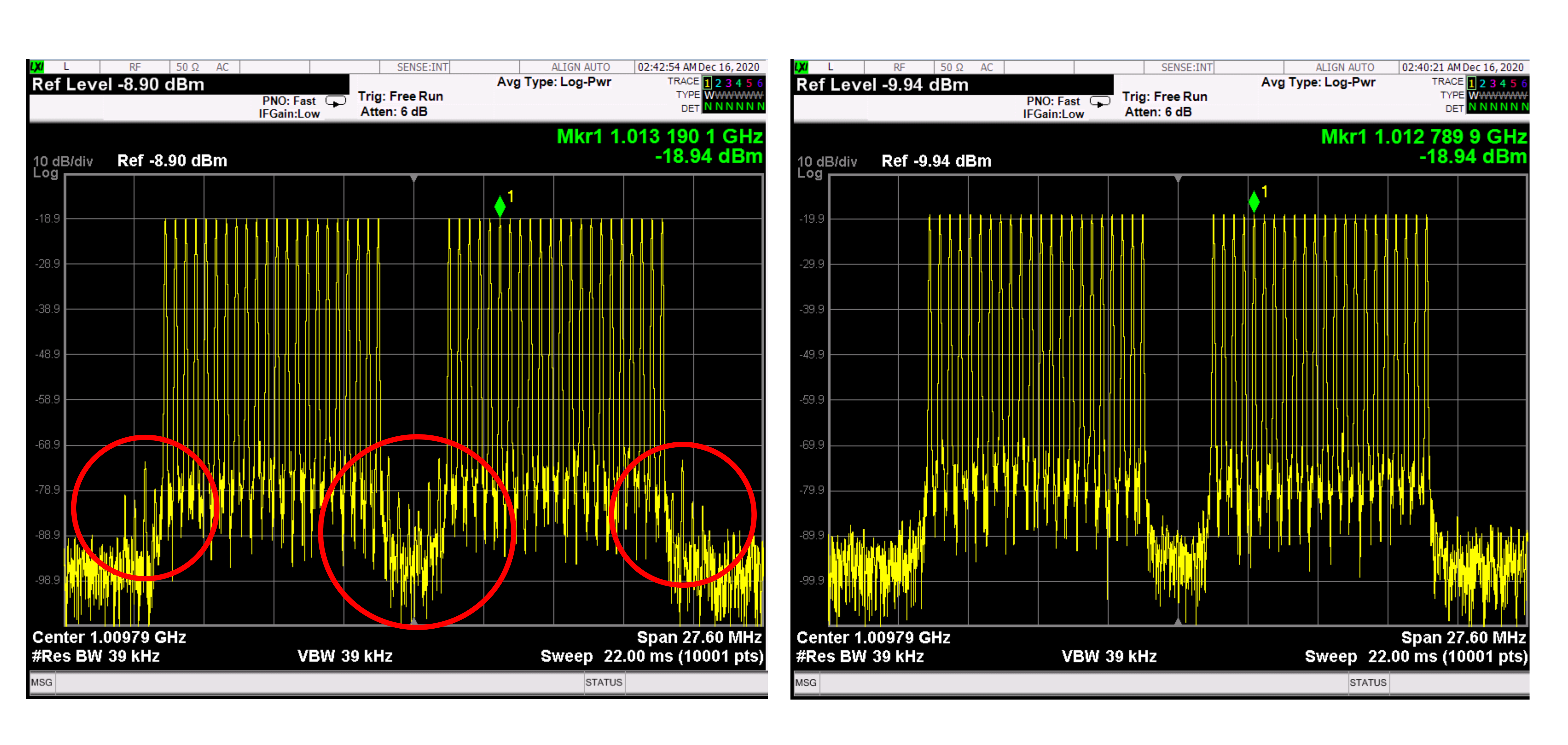
Figure 2.4: Multiple correction techniques can be applied to improve the SNR of the generated signals and is equivalent to use a higher ENoB DAC. Noise shaping techniques, where noise is removed from some bands of the spectrum, is one of these techniques. In this example, the “nulling-tones” technique is used. On the left, an uncorrected bandwidth-limited multi-tone signal with a notch is shown. IMD products are clearly visible in the notch and the adjacent channels (circled in red). On the right, after applying the “nulling-tone” technique, the SFDR has been improved by over 20dB, and the IMD products are buried in the noise - improving the dynamic range of any NPR test.
The frequency response of an AWG can also impact the ENoB performance as the amplitude frequency response for most AWGs goes down as frequency increases. The reduced amplitude at higher frequencies results in the reduction of the ENoB. However, we live in a world of wideband signals such as WLAN, 5G and UWB, therefor to maintain excellent flatness linear correction of the frequency response is required. Corrections in theory boost the higher frequency components while keeping the amplitude of the lower frequency components. However, you cannot boost the signal amplitude more than the DAC range, so in reality, you reduce the overall amplitude of the lower frequencies (renormalization). This yields a new corrected signal with a lower amplitude than the original one. Yet SINAD stays the same effectively reducing the ENoB for the lower frequency components (one bit for every 6dB of loss). This must be understood as a trade-off, as in some cases better frequency response may be much more valuable in terms of signal generation accuracy than extra effective bits.
Part 4 - Sample Resolution vs. DAC Resolution
For more information: [email protected]