
- Signal Fidelity - Choose the correct sample rate vs waveform characteristics
Today, modulated signals are used in almost every existing communication method. They are found in many industries such as mobile phones, radars, lasers, Wi-Fi networks, modems, navigation systems (GPS), RFID tags and satellite communications. Same modulation schemes can be found in wired communication systems as well. Signal modulation techniques are also being used to excite particles in various physics research fields such as quantum computing.
The rapid advancement of technology demands larger quantities of information to be transferred at a faster pace. Therefore, scientists, researchers & engineers will always attempt to use higher bandwidths. Due to this continuous growth in the amount of data being transferred by communication systems, more advanced and complicated modulation schemes are being implemented, making the generation of IQ modulated signals, a challenge. A need for simulating user defined data signals with higher frequencies & larger bandwidths always arises. Therefore, signal sources, such as AWGs, play an essential role in the test and validation of new receiver designs and of electrical components for many different applications such as for MIPI, USB & Radars.
Data transfer is done by Modulating one of the three signal’s characteristics:
- Amplitude modulation – Using AM, the amplitude of a high-frequency carrier signal is varied in proportion to the instantaneous amplitude of the modulating message signal.
- Frequency Modulation – Using FM, the amplitude of the modulating carrier is kept constant while its frequency is varied by the modulating message signal.
- Phase Modulation – Using PM, the phase of the modulating carrier is varied by the modulating message signal.
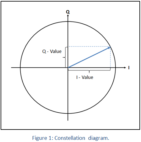
In implementations such as in digital communications, amplitude and phase can be modulated simultaneously. This way, the baseband signal (the data signal) is separate
d into two orthogonal components: In-phase and Quadrature. A polar representation of it will be as a vector that has a magnitude and an angle, and the carrier signal becomes a frequency and phase reference for the data signal. The magnitude of the data signal is either abs
olute or relative to the carrier’s magnitude.
Requirement
Satellite communications, smart-phones, DOCSIS, WiFi, WiGig and many other uses various digital modulation schemes, to transfer data. Some of those are using single carrier techniques and others may require the use of high-quality OFDM signals. OFDM signals require wider channel bandwidth, low phase noise and additionally, require sequencing abilities of as many different symbols as possible.
Some wireless standards use channel coding such as error correction. Some tests require changing the order of the data being sent. For example, in WiGig, the digital signal may consist of a QAM modulated carriers, but a readable frame requires the transmission of each data packet with certain bytes before and after (for example error protection bytes). The same considerations apply to other wireless networks such as WiFi.
Generating such signals requires storing a great number of symbols in the waveform memory and therefore requires large record lengths. To conclude, the requirement is for an arbitrary generation capability that can support as many realistic channel-coding requirements as possible.
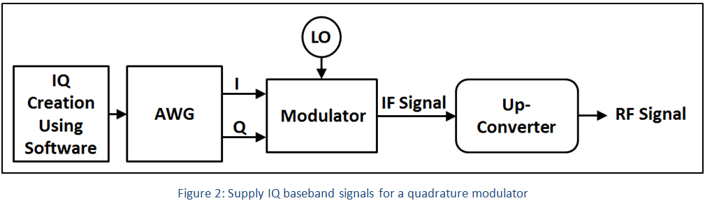
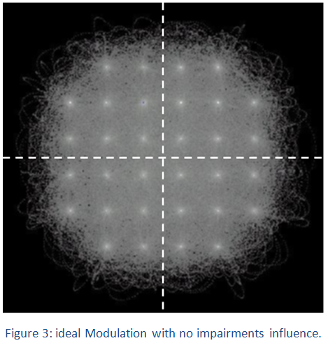
For supplying high precision baseband signals to feed a quadrature modulator (Figure 2) or for direct creation of the modulated RF carrier, one would need to use a Two-channel Arbitrary waveform generator.
Using AWGs as part of a system, one could generate accurate IF/RF signals in 2 different ways:
I. Using analog I-Q modulator – This can be accomplished in two ways. Both are using a two channel AWG to produce the baseband signals I & Q:
- One approach for applying this modulation, is to use a Vector Signal Generator to both generate and shape the IF signal. The modulation is taken care of internally, and one only needs to supply the baseband signals (I & Q) using a two-channel AWG.
- The second approach is by replacing the Vector Signal Generator with much cheaper components, using a combination of mixers, filters, a power amplifier and other components, along with the two channels AWG as the I&Q source and a Signal Generator as the local oscillator to produce the IF signal. This setup can deliver essentially indistinguishable or better performance at lower cost.
An external modulator/VSG accepts two basebands signals of the same frequency with a 90° phase difference and a carrier waveform crea
ted by an internal/external local oscillator. A perfect quadrature modulator produces a single carrier of 𝑓𝑐−𝑓𝑚 or 𝑓𝑐+𝑓𝑚 when two sinusoidal signals with the same 𝑓𝑚 frequency 𝑓𝑚 and 90° relative phase are applied to its I & Q entries. The resulting IF signal will be a single side band (SSB) carrier with constant amplitude envelope.
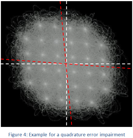
Any impairments between the I and Q signals will impact the modulation accuracy.
Differences may arise from:
1. QUAD. ERROR - Quadrature error refers to the phase deviation between the I and Q axis relative to the ideal phase (90°).
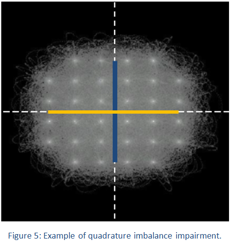
2. QUAD. IMBALANCE - Quadrature imbalance refers to the amplitude deviation between the I and Q components of the signal relative to the ideal one (same amplitude).
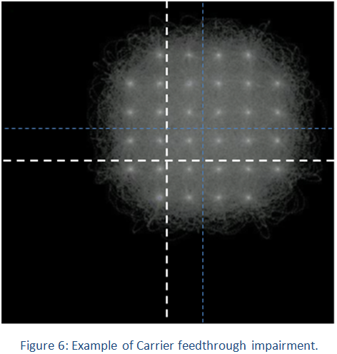
3. C. FEEDTRHOUGH - Carrier feed through consists in an undesired added DC component to the base band signals.
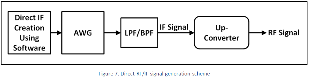
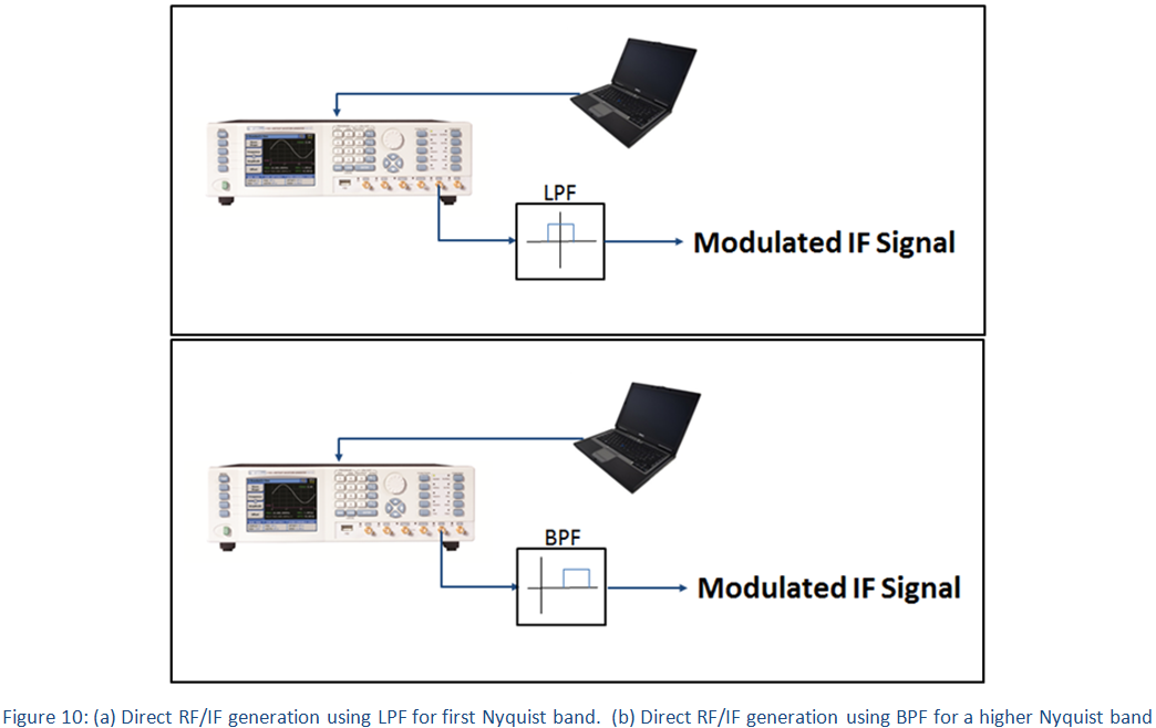
II. Direct IF generation - Directly generate one or multiple modulated carriers at the RF frequency or at an intermediate frequency (IF). Using a dedicated filter, it is possible to capture the signal image in higher Nyquist bands, thus enable generation at higher carrier frequencies.
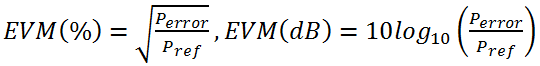
Noise, distortion, spurious signals, and phase noise all degrade the quality of the modulation being generated. A method of measuring the accuracy of the generated modulation is to measure the Error Vector Magnitude or EVM.
Error Vector Magnitude (EVM) – This measurement shows the error vector (difference) between an ideal constellation point and the transmitted/received point on the IQ plane:
The impairments that may affect the EVM:
- Phase/Frequency Accuracy
- Quadrature Error/Quadrature Imbalance
- DC/Carrier Feedthrough
- Jitter & noise
Solution
Tabor Electronics High-speed AWGs enables the user to generate I and Q components and even allows direct creation of multiple IF modulated carriers of any modulation scheme using its multi –Nyquist zones operation.
- Tabor Electronics High speed AWGs specifically designed for IQ baseband signal generation, such as the WX2182C, WX2184C or the SE5082, combined with a high-quality quadrature modulator, allow for the generation of accurate modulated signals with up to 5 GHz of modulation bandwidth.
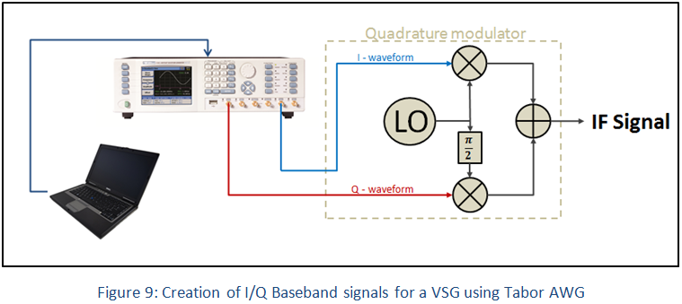
In an SSB modulation generated using a dual channel Tabor AWG as can be seen in figure 8, the output of each mixer is a dual side band signal. The two signals are summarized, which results in the cancellation of one of the sidebands. Actual quadrature modulators are not perfect and there are unwanted impairments between the I and Q components. This could be easily adjusted & fine-tuned using Tabor AWG’s.
- Tabor Electronics high speed AWGs such as the SE5082 with a high sampling rate and excellent SFDR performance can directly generate multiple modulated IF/RF carriers.
Multi Nyquist-zones
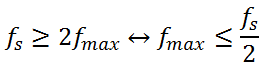
The Nyquist Sampling Theorem states that the sampling rate of a signal must be at least twice the rate of the highest frequency component. Translated to the world of arbitrary waveform generators, in order to produce a signal of maximum frequency 𝑓𝑚𝑎𝑥, the sampling rate 𝑓𝑠 must be at least 2𝑓𝑚𝑎𝑥. Alternatively, the highest frequency signal a DAC with sampling frequency 𝑓𝑠 can generate, is equal to half the sampling rate or 𝑓𝑠/2 (referred to as the first Nyquist zone).
In the frequency domain, when generating a sinus waveform of frequency fo it will appear as a spectral component at fo. However, there will be additional frequency products often referred to as images, at higher frequencies. These products are a function of the sampling rate and fo and are described by:

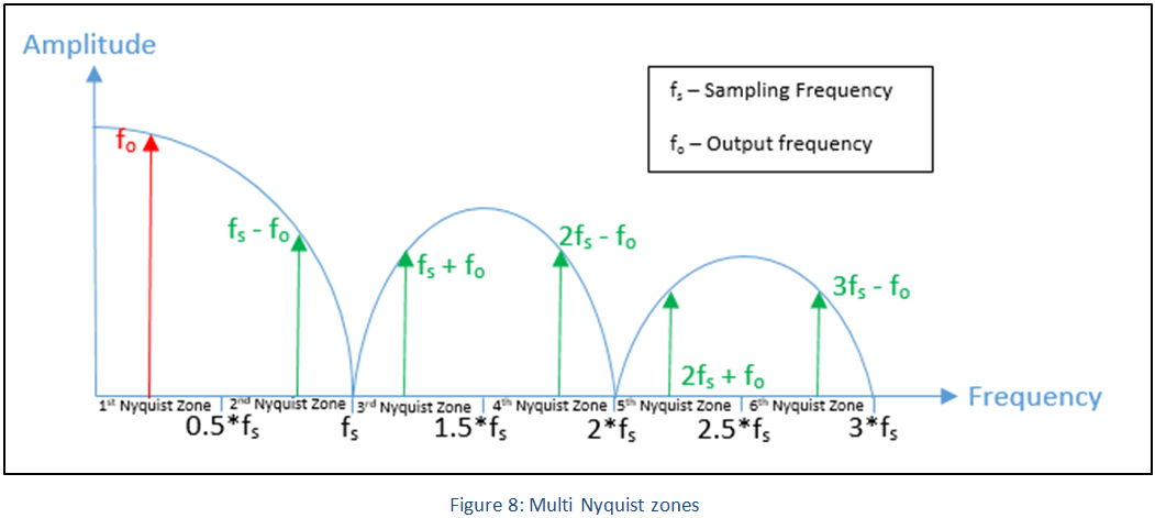
Traditionally, DACs analog BW is not much higher than the BW of the first Nyquist zone causing suppression of signals at higher Nyquist zones. The new DAC used in the Signal Expert series offers an exceptionally wide bandwidth reaching up to 7GHz. In addition, using different sampling methods, the DAC can optimize performance at higher Nyquist zones so that the higher frequency images are not suppressed. Therefore, even though the DAC is sampling at 5GS/s, the images at higher Nyquist zones are passed through. Using a proper Bandpass filter, users can filter the unrequired frequency products and essentially generate signals at much higher frequencies.
The new Tabor Electronics Signal-Expert Arbitrary Waveform Generator offers the best performance than any other unit on the market in its price range, featuring:
- 5Gs/s, 12 bit dual channel waveform generators
- Extra wide analog bandwidth of more than 7GHz
- Extremely fast rise and fall time of under 150ps
- Multi-Nyquist zone operation capability, up to the 4th Nyquist zone
- Selectable sampling modes for optimizing performance depending on the required Nyquist zone
- Independent or synchronized channels with 10ps inter channel skew resolution
- Up to 64M of waveform memory
- Various output amplifier modules utilized to solve numerous applications in different domains
- Smart trigger enables trigger hold-off, detect, wait, abort and restart
- Advanced sequencer for step, loop, nest and jumps scenarios
- Built-in fast dynamic segments and sequences hop control
- Two programmable markers (positions, width and levels) per channel
- Multi instrument synchronization
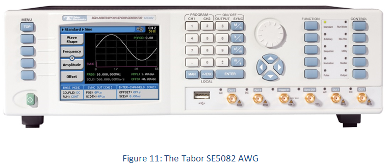
The Signal Expert AWG enables the generation of extremely long pulse sequences for IQ modulation. With a waveform memory of up to 64Mb per channel, with sequence and advance sequence modes, users can define the order and duration of each symbol with nesting and looping of each stored pulsed level (may also be referred to as a stored segment). Users can also define when to jump to the following segment with conditional jumping on events. The Tabor SE5082 draw special interest for use in I-Q applications due to excellent low noise performance, controllable channel delay & skew resolution of 10ps, the ability to control & fine tune the amplitude of each outputted channel, and finally the sequencing capabilities that allows separate advance sequence table (playlist of playlists) to be downloaded to each channel.
Pulse sequencing for IQ on the Tabor SE5082 can be created using MATLAB, Python, C++, LabVIEW or by simply using the ArbConnection, which is a custom made remote control software, provided free of charge by Tabor Electronics. The ArbConnection allows the user to unleash the virtually unlimited waveform generation capabilities built into the Tabor SE5082.
Applications

For More Information
To learn more about Tabor’s solutions or to schedule a demo, please contact your local Tabor representative or email your request to [email protected]. More information can be found at our website at www.taborelec.com