- Signal Fidelity - Choose the correct sample rate vs waveform characteristics
Chirp Modulation is required by applications in which the frequency of the signal increases or decreases with time. The Tabor family of Arbitrary Waveform Generators (AWGs) generates waveforms that “sweep” from a starting frequency to an ending frequency, while supporting an amplitude sweep as well. This document will quickly guide you through the definition process.
NOTE
You can also generate Amplitude Modulation, Frequency Modulation, and Sweep Modulation by following steps similar to those described in this document.
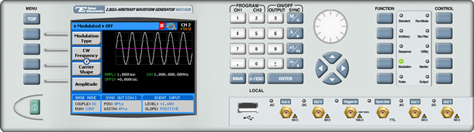
The front panel of the AWG is depicted below.
- To generate a Chirp Modulation using the front panel:
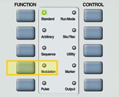
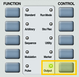
1. Press the Modulation button in the function menu.
2. Press the Modulation Type menu button. A list of modulation types appears on the screen. By default, the modulation type is set to “OFF”.
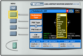
3. Select the Chirp modulation type from the list box using the arrow keys, and press ENTER.
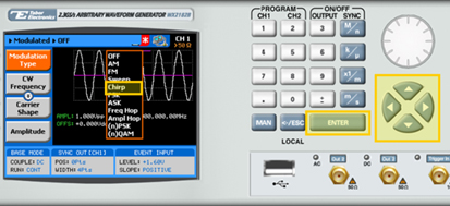
4. Following your selection, you will be able to configure the characteristics of the modulation with the modulation-type specific menu buttons that appear on the left-hand side of the panel.
TIP
Whenever the arrows icon is displayed there are more attribute menu buttons to be shown below. Simply scroll down using the dial or cursor key.
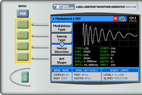
5. Choose the menu buttons on the left-hand side of the screen to modify any of the following attributes:
- Sweep Type. Specifies a linear or a logarithmic sweep.
- Sweep Direction. Up or Down.
- AM Shape. Specifies linear or logarithmic amplitude steps.
- AM Direction. Up or Down.
- Start Frequency. The frequency at which the sweep starts. The start frequency can be either the low or the high frequency, depending on the sweep direction.
- Stop Frequency. The frequency at which the sweep stops. The stop frequency can be either the low or the high frequency, depending on the sweep direction.
- Pulse Width. The time lapse set between the start of the chirp and the end of the chirp.
- Pulse Repetition. The time lapse set between the start of the chirp and the start of the following chirp.
- AM Depth. Defines amplitude depth as a percentage of the full VDC amplitude span. 100% represents the full amplitude span, while 0% represents “no signal”.
- Marker. Defines the frequency at which the Sync Output generates a pulse (available for sweep and FM modulations only).
- Carrier Shape. The shape of the carrier wave – for example, a sine wave, triangle, or square.
- Amplitude. The amplitude of the carrier wave (in Volts peak-to-peak).
- Offset. The amplitude (in VDC) offset with reference to zero-level amplitude.
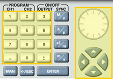
6. When selecting a numeric attribute for modification, modify the displayed value using the dial or the cursor keys, or by entering the value using the numeric keypad. Press ENTER to save the modified parameter value.
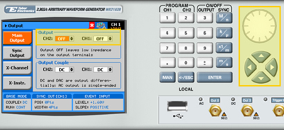
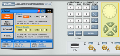
7. Press the Output button in the control menu to configure the output settings.
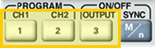
8. Define the channels in the Output section as being ON or OFF, modifying the settings using the dial or the cursor keys.
TIP
You can quickly modify the output settings by selecting CH1 or CH2 on the keypad, and toggling the OUTPUT key to turn the channel on or off.
9. Select the output path of the channels in the Output Couple section, modifying the settings using the dial or the cursor keys.
- DC (2Vp-p into 50Ω DC coupled)
- HV (High-Voltage 4Vp-p into 50Ω DC coupled)
- AC (-20 to +10 dBm into 50Ω AC coupled)
Press ENTER to save the output settings.
For More Information
To learn more about Tabor’s solutions or to schedule a demo, please contact your local Tabor representative or email your request to [email protected]