The Tabor family of Arbitrary Waveform Generators allows you to generate output waveforms continuously, or in response to external signals. This document will help you to quickly set one of the following run modes:
- Continuous Mode, in which the AWG generates waveforms at its output terminals continuously – without a specified starting or stopping point.
- Triggered Mode. In triggered mode, output remains at a specific DC level and waits for a valid trigger event to initiate a complete output waveform. At the end of the output cycle, the output resumes position at a DC level that is equal to the amplitude of the first point of the waveform.
- Gated Mode, in which the output remains at a DC level and waits for a valid gate event to output waveforms. When the gate closes, the output completes the waveform and returns to a DC level that is equal to the amplitude of the first point of the waveform.
The front panel of the AWG is depicted below.
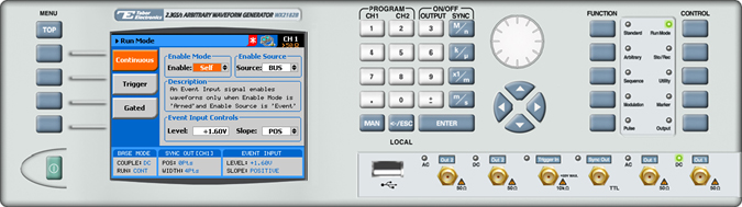
To set a run mode, press the Run Mode button in the Controlmenu.
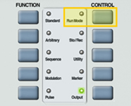
Select the run mode by pressing on one of the following menu buttons:
- To configure continuous output:
1. Press the Continuous button in the function menu.
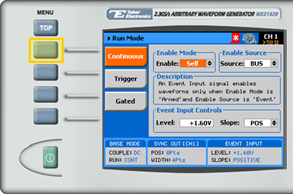
2. Select the Enable mode:
- Self. The generator is self-armed. In this mode, waveforms are generated continuously at the output terminals as soon as the output function is selected and the output is turned on.
- Armed. In this mode, the generator transitions from idle to waveform generation immediately upon receipt of an enable signal, and ceases waveform generation immediately upon receipt of an abort signal.
3. If Armed mode was selected, choose an enable Source to specify the source of the enable signal.
- BUS. The enable signal is sent using remote PC commands.
- EVENT. An external source transmits the enable signal via the AWG’s rear-panel, Event-In connector.
- TRIG. The enable signal is triggered using the front panel.
4. If the EVENT source was chosen, specify Event Input Controls.
- Level. The threshold level, within the range -5V to +5V.
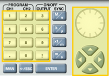
When selecting a numeric attribute for modification, modify the displayed value using the dial or the cursor keys, or by entering the value using the numeric keypad. Press ENTER to save the modified parameter value.
- Slope. The transition type, either POS (rising), NEG (falling), or EITHER.
- To configure triggered output:
1. Press the Trigger menu button in the Run Mode menu.
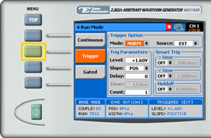
2. Select the Trigger mode:
- NORM. In normal trigger mode, every trigger generates a waveform (segment) cycle. However, new triggers are ignored for the duration of the current waveform output.
- OVER. In override mode, a new trigger immediately restarts the current waveform (segment), regardless of whether the current waveform cycle has been completed or not.
3. Select the trigger Source.
- BUS. The trigger is input using remote PC commands.
- INT. The trigger is generated internally in the AWG.
- EVENT. Enables triggering via the AWG’s rear panel Event In connector.
- EXT. The trigger is input using the front panel Trig In connector.
4.Specify the Trig Parameters.
- Level. The threshold level for the trigger input, ranging from -5V to +5V.
- Slope. The transition type, either POS (rising), NEG (falling), or EITHER.
- Delay. Delays the trigger by the number of samples specified in the field. A delay of “0” disables the delay mechanism.
- Timer. Sets a fixed interval from each waveform start to the next waveform start, ranging from 200 ns to 2 seconds.
- Count. The number of output cycles to be generated from a single trigger, ranging from 1 to 1 million.
5. Enter Smart Trigparameters to accept only those triggers with specified pulse widths.
- > Time. If “ON”, triggers with pulse widths greater than the time specified are accepted.
- < Time. If “ON”, triggers with pulse widths less than the time specified are accepted.
If both the > Time and the < Time fields are marked “ON”, triggers with pulse widths between the times specified are accepted.
- Holdoff. Specifies the time interval following a trigger during which the system ignores additional triggers. Following the time interval, new triggers are accepted.
- To configure gated output:
1. Press the Gated menu in the Run Mode menu.
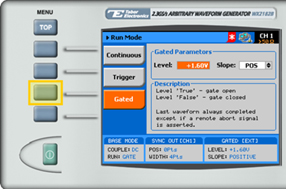
2. Specify the Gated Parameters.
- Level. The threshold level for the gating signal, ranging from -5V to +5V.
- Slope. The transition type, either POS (rising), or NEG (falling).
If set to POS, a rising input opens the gate, while a falling input closes the gate.
If set to NEG, a falling input opens the gate, while a rising input closes the gate.
For More Information
To learn more about Tabor’s solutions or to schedule a demo, please contact your local Tabor representative or email your request to [email protected]