The Tabor family of Arbitrary Waveform generators allows you to generate output waveforms continuously, or in response to external signals. This document will help you to quickly set one of the following run modes:
- Continuous Mode, in which the AWG generates waveforms at its output terminals continuously – without a specified starting or stopping point.
- Triggered Mode, in which the output remains at a specific DC level and waits for a valid trigger event to initiate a complete output waveform. At the end of the output cycle, the output resumes position at a DC level that is equal to the amplitude of the first point of the waveform.
- Gated Mode, in which the output remains at a DC level and waits for a valid gate event to output waveforms. When the gate closes, the output completes the waveform and returns to a DC level that is equal to the amplitude of the first point of the waveform.
- Burst Mode, is an extension of the triggered mode in which the AWG can be programmed to output a pre-determined number of waveforms.
NOTE
The Trigger options described in this document are available in the WW2571/2A, WW5064/1074/2074, WS8101/2 and PM8571/2A models.
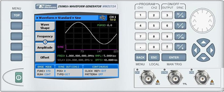
The front panel of the AWG is depicted below.
- To set a Run Mode using the front panel:
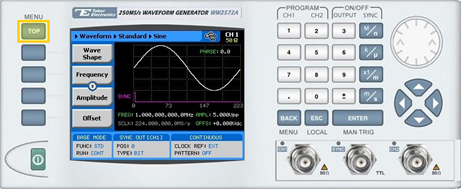
1. Press the TOP menu button.
2. Press the Run Mode button.
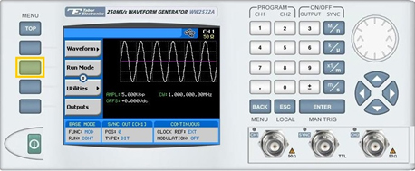
3. Select the Run Mode by pressing on one of the following menu buttons:
- Continuous
- Trigger
- Gated
- Burst
- To configure continuous output:
1. Continuous is the default run mode of the unit. The selected waveform is output continuously when the output is turned ON.
- To configure triggered output:
1. Press the Triggered button.
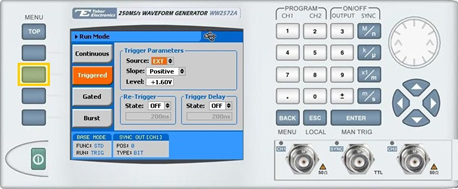
2. Specify the Trigger Parameters.
- Source. Select the triggersource:
- BUS. The trigger is input using remote PC commands.
- EXT. The trigger is input via the TRIG IN connector or the MAN TRIGcontrol.
- MIX. Special trigger behavior, in which the system waits for a remote bus trigger and only then enables the hardware sources.
- Slope. The transition type, either POS (rising), or NEG (falling).
- Level. The threshold level for the trigger input, ranging from -5V to +5V.
3. Set the Re-Trigger parameters.
- State. Used to enable/disable (ON/OFF) the re-trigger function. If enabled, enter the time interval between the end of a signal to the start of the next signal.
4. Set the Trigger Delay parameters:
- State. Used to enable/disable (ON/OFF) the delay mechanism. If enabled, enter the amount of time to delay output signals following a trigger.
- To configure gated output:
1. Press the Gated button.
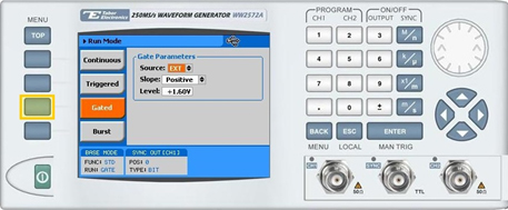
2. Specify the Gated Parameters.
- Source. Select the gatedsource:
- BUS. The trigger is input using remote PC commands.
- EXT. The trigger is input via the TRIG IN connector or the MAN TRIG control.
- MIX. Special trigger behavior, in which the system waits for a remote bus trigger and only then enables the hardware sources.
- Slope. The transition type, either POS (rising), or NEG (falling).
- If set to POS, a rising input opens the gate, while a falling input closes the gate.
- If set to NEG, a falling input opens the gate, while a rising input closes the gate.
- Level. The threshold level for the gating signal, ranging from -5V to +5V.
- To configure burst output:
1. Press the Burst button.
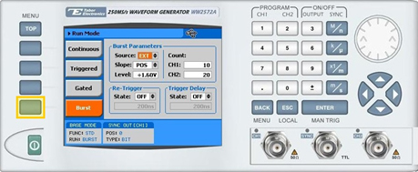
2. Specify the Burst Parameters.
- Source. Select the trigger source:
- BUS. The trigger is input using remote PC commands.
- EXT. The trigger is input via the TRIG IN connector or the MAN TRIG control.
- MIX. Special trigger behavior, in which the system waits for a remote bus trigger and only then enables the hardware sources.
- Slope. The transition type, either POS (rising), or NEG (falling).
- Level. The threshold level for the trigger input, ranging from -5V to +5V.
3. Set theRe-Trigger parameters.
- State. Used to enable/disable (ON/OFF) the re-trigger function. If enabled, enter the time interval between the end of a signal to the start of the next signal.
4. Set the Trigger Delay parameters:
- State. Used to enable/disable (ON/OFF) the delay mechanism. If enabled, enter the amount of time to delay output signals following a trigger.
5. Set the Count parameters with the number of waveform cycles to output per trigger signal.
For More Information
To learn more about Tabor’s solutions or to schedule a demo, please contact your local Tabor representative or email your request to [email protected].