The Tabor family of Arbitrary Waveform Generators (AWGs) allows you to program arbitrary waveform segments that can be combined in any sequence. This document will quickly guide you through the definition process.
NOTE
In order to program more complex arbitrary waveforms, use the Tabor ArbConnection software-based wave composer tool.
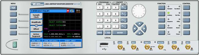
The front panel of the AWG is depicted below.
- To generate an arbitrary waveform using the front panel:
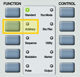
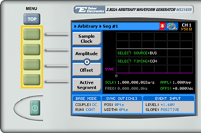
1. Press the Arbitrary button in the function menu.
2. Press the Active Segment menu button to select the index number of the segment to be edited. Enter the number of the segment to be edited and press ENTER.
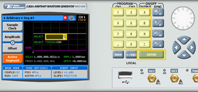
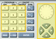
3. When selecting a numeric attribute for modification, modify the displayed value using the dial or the cursor keys, or by entering the value using the numeric keypad. Press ENTER to save the modified parameter value.
4. Modify the arbitrary waveform using menu buttons that appear on the left-hand side of the panel.
TIP
Whenever the arrows icon is displayed there are more attribute menu buttons to be shown below. Simply scroll down using the dial or cursor key.
5. Choose a menu buttons to modify any of the following attributes:
- Sample Clock. Specifies the sample clock frequency, measured in samples/second.
- Power. Specifies the output power of the waveform. This parameter is available for
AC-coupled output paths only.
- Amplitude. The amplitude of the waveform (in Volts peak-to-peak). This parameter is not available for AC-coupled output paths.
- Offset. The amplitude offset (in Volts peak-to-peak) with reference to zero-level amplitude. This parameter is not available for AC-coupled output paths.
- Active Segment. The number of the arbitrary waveform segment that is currently active in working memory.
- Jump Event. Selects the source that will trigger segment transitions.
• Bus. Selection of segments is controlled by remote PC commands.
• External. An external source dynamically asserts control via the AWG’s rear-panel, 9-pin control connector.
- Jump Timing. Defines the transition type.
• Coherent. The currently running segment is completed before switching to the next segment.
• Immediate. The currently running segment is immediately terminated and the newly selected segment begins.
- Wave Composer. Allows you to define the arbitrary waveform shape that is stored in the selected segment. See step 6.
- Delete Segments. Removes the table that defines start and stop addresses for each segment location.
6. Press the Wave Composer menu button to define and edit an arbitrary waveform segment, as shown below.
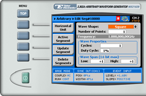
The Wave Composer offers the following menu buttons:
- Horizontal Unit. Used to select the horizontal unit type. Choose Sample Clock, Frequency, or Period.
- Active Segment. Selects an arbitrary waveform segment for editing.
- Update Segment. Saves the modifications made to the selected arbitrary waveform segment.
- Delete Segments. Removes the table that defines start and stop addresses for each segment location.
7. Modify any of the segment’s attributes:
- Wave Shape. Choose Square, Sine, Triangle, Sinc, Gaussian, Exponential or Random Noise.
- Number of Points. The length of the segment in points.
- Cycles. The number of cycles that will be created in the selected segment.
- Wave shape specific parameter. Sets the parameter relevant for the chosen waveshape, eg. Phase for Sine wave.
- Wave Span. The low and high level values of the DAC (Digital-to-Analog Converter), ranging from -8192 to +8191.
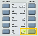
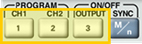
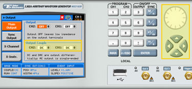
8. Press the Output button in the control menu to configure the output settings.
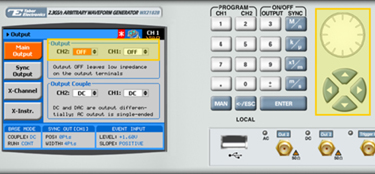
9. Define the channels in the Output section as being ON or OFF, modifying the settings using the dial or the cursor keys.
TIP
You can quickly modify the output settings by selecting CH1 or CH2 on the keypad, and toggling the OUTPUT key to turn the channel on or off.
10. Select the output path of the channels in the Output Couple section, modifying the settings using the dial or the cursor keys.
• DC (2Vp-p into 50Ω DC coupled)
• HV (High-Voltage 4Vp-p into 50Ω DC coupled)
• AC (-20 to +10 dBm into 50Ω AC coupled)
Press ENTER to save the output settings.
For More Information
To learn more about Tabor’s solutions or to schedule a demo, please contact your local Tabor representative or email your request to [email protected]