Sequenced waveforms are constructed from two or more arbitrary waveform segments. The Tabor family of Arbitrary Waveform Generators (AWGs) allows you to program individual segments, and then combine them using the sequencing function. This document will quickly guide you through the definition process.
NOTE
Waveform segments must be generated before constructing a sequence. See How to Simply Generate an Arbitrary Waveform for further information.
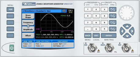
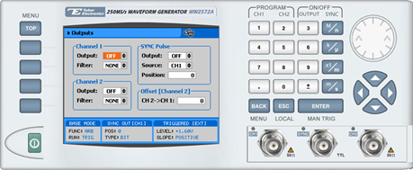
The front panel of the AWG is depicted below.

- To generate a sequence using the front panel:
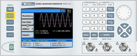
1. Press the TOP menu button.
2. Press the Waveform menu button.
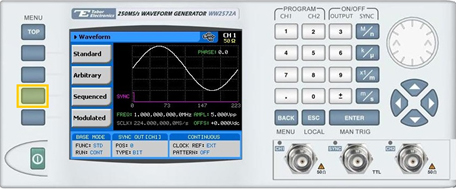
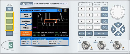
3. Press the Sequenced menu button.
4. Press the Active Sequence menu button to select the index number of the sequence to be defined.
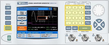
Enter the number of the sequence to be edited and press ENTER. Up to 10 sequences can be stored in the system, recalled, and replayed*.
NOTE
The sequence storage feature is not applicable for the WW5061/2 and WW1071/2 models
5. Following your sequence selection, you will be able to modify the sequence using the sequencing-specific menu buttons that appear on the left-hand side of the panel.
TIP
Whenever the arrows icon is displayed there are more attribute menu buttons to be shown below. Simply scroll down using the dial or cursor key.
6. Choose the menu buttons on the left-hand side of the screen to modify any of the following attributes:
- View Table. A table used to program the sequence in which the arbitrary waveform segments will be generated, as explained in step 7.
- Advance Mode. Select the method for advancing to the next segment in the table:
- Automatic. Automatic advancement to the next step (as long as a Adv Bit flag has not been set). At the end of the sequence, the sequence is repeated from the beginning
- Step. In this mode, an Adv Bit flag is appended to each step in the sequence. Therefore, advancement to the next step occurs only following assertion of a jump event signal.
- Mixed. Utilizes a sequence table with a combination of automatic and stepped segments.
- Advance Source. Defines which of the trigger inputs will advance the sequence.
- Bus. Trigger sent by remote PC command.
- External. External trigger source.
- Internal. Internal trigger of the unit.
- Sample Clock. Specifies the sample clock frequency, measured in samples/second
- Amplitude. The amplitude of the sequenced waveform (in Volts peak-to-peak).
- Offset. The amplitude offset (in Volts peak-to-peak) with reference to zero-level amplitude.
- Active Sequence. Specifies the number of the active sequence.
- Active Segment. Programs the active segment in a sequence. The SYNC will start at the active segment.
- Sync Type. Specifies the sync output in sequence mode.
- BIT. The sync output will generate a pulse at the beginning of a specific segment regardless of how many times the segment appears in a sequence. The width of the sync pulse is 16 waveform points.
- LCOM. The sync output will transition high at the beginning of the sequence and will transition low at the end of the sequence, less 16 waveform points.
NOTE
Some of the menu buttons or sequence table parameters described in this document may not be present on your WW device as the sequence capabilities vary between the different WW units.
7. Press the View Table menu button to program a sequence of arbitrary waveform segments, as shown below.
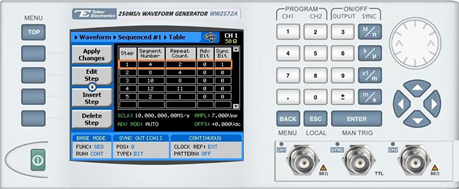
Each row in the table includes the following parameters:
- Step. The index number of the row.
- Segment Number. The segment number of the arbitrary waveform to be replayed.
- Repeat Count. The number of times the segment is to be replayed.
- Adv Bit. For stepped advance mode only. When set to “0”, the sequence will advance through the list automatically until a segment that is flagged “1” is encountered. When “1” is encountered, the generator will idle on this segment until an external trigger is applied.
- Sync Bit. “1” programs bit present at a specific sequence step.
NOTE
A minimum segment duration is required for a sequence to be valid. The required duration can be found in the specification sheet of the relevant WW unit.
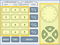
8. After selecting a numeric attribute for modification, modify the displayed value either by using the dial or the cursor keys, or by entering the value using the numeric keypad and suffix key. Press ENTER to save the modified parameter value.
9. Press the TOP menu button to return to the main menu.
10. Press the Outputs menu button to configure the output settings.
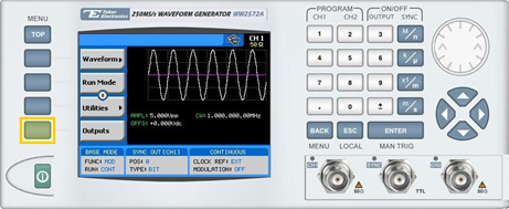
11. Define the channels in the Outputs section as being ON or OFF, modifying the settings using the dial or the cursor keys:
- To scroll between the fields, use the cursor keys.
- To edit a field, select the field, and press ENTER. Use the keypad to enter the chosen value.
- To toggle between ON and OFF, select the OUTPUT field and press ENTER. Use the cursor keys to choose the selected option.
- Press ENTER again to exit the edit mode, and save the value.
TIP
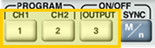
You can quickly modify the output settings by selecting CH1 or CH2 on the keypad, and toggling the OUTPUT key to turn the channel on or off.
For More Information
To learn more about Tabor’s solutions or to schedule a demo, please contact your local Tabor representative or email your request to [email protected]