A pulse train is a series of generated pulses. The pulses in a pulse train can be identical or unique.
The Tabor family of Arbitrary Waveform Generators (AWGs) is designed for easy programming of pulse trains. This document will quickly guide you through the process of pulse train generation.
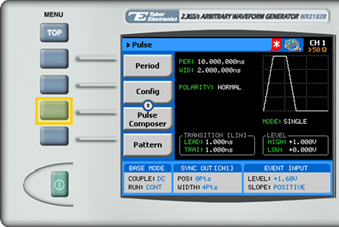
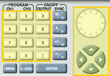
The front panel of the AWG is depicted below.
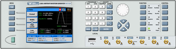
- To generate a pulse train using the front panel:
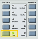
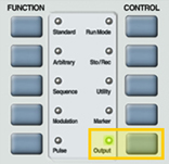
1. Press the Pulse button in the function menu.
2. To generate a regular pulse please refer to the How to Simply Generate a Pulse solution note. To generate a pulse train, scroll down to the bottom of the menu and select the Pulse Composer menu button.
TIP
Whenever the arrows icon is displayed there are more attribute menu buttons to be shown below. Simply scroll down using the dial or cursor key.
3. Here you can program the pulse train with the table displayed. There are two types of pulse trains that can be programmed depending on the transition type selected. To select the transition type, scroll down to the bottom of the menu and press the Transition Type menu button.
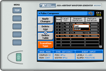
- Fast. User programs only the DC level and the duration time of that level, all transitions are done as fast as possible.
- Linear. User programs initial level, final level and the transition time between them.
4. In Fast transition program the series of pulses, as shown below.
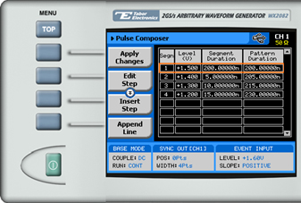
Use the Edit Step, Insert Step, Append Line or Delete Line menu buttons to edit the table.
Each row in the table includes the following parameters:
- Segm. The index number of the segment.
- Level. The voltage level of the pulse.
- Segment Duration. The duration of the segment, in units of time.
- Pattern Duration. The accumulated duration of the pulse pattern, in units of time.
5. In Linear transition program the series of pulses, as shown below.
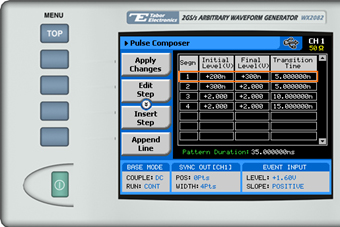
Use the Edit Step, Insert Step, Append Line or Delete Line menu buttons to edit the table.
Each row in the table includes the following parameters:
- Segm. The index number of the segment.
- Initial Level. The initial voltage level of the pulse.
- Final Level. The final voltage level of the pulse.
- Transition Time. The duration of the level transition in time.
6. After selecting the attribute for modification, modify the displayed value using the dial or the cursor keys, or by entering the value using the numeric keypad. Press ENTER to save the modified parameter value.
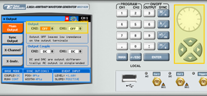
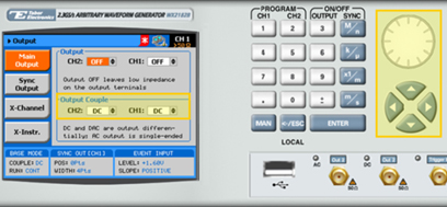
7. Press the Output button in the control menu to configure the output settings.
8. Define the channels in the Output section as being ON or OFF, modifying the settings using the dial or the cursor keys.
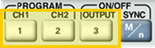
TIP
You can quickly modify the output settings by selecting CH1 or CH2 on the keypad, and toggling the OUTPUT key to turn the channel on or off.
9. Select the output path of the channels in the Output Couple section, modifying the settings using the dial or the cursor keys.
- DC (2Vp-p into 50Ω DC coupled)
- HV (High-Voltage 4Vp-p into 50Ω DC coupled)
- AC (-20 to +10 dBm into 50Ω AC coupled)
Press ENTER to save the output settings.
For More Information
To learn more about Tabor’s solutions or to schedule a demo, please contact your local Tabor representative or email your request to [email protected]