The Tabor family of Arbitrary Waveform Generators (AWGs) is designed for easy programming of pulses and pulse characteristics. This document will quickly guide you through the process of pulse generation.
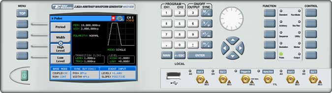
The front panel of the AWG is depicted below.
- To generate a pulse using the front panel:
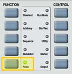
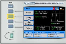
1. Press the Pulse button in the function menu.
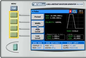
2. Now that you have chosen to generate a pulse, you can press the menu buttons on the left-hand side of the panel to select an array of pulse attributes for modification. The actual list of displayed buttons can vary depending on the pulse setup as selected in the Config menu (see step 0). The various possible pulse attributes that can be set are:
- Period. The time interval between the start of a pulse and the start of the following pulse.
- Width. The period of the time during which the pulse remains at its high-voltage level.
- High Level. The high-level voltage value. This button appears when High/Low or Positive is selected in the Config >> Level Control menu.
- Low Level. The low-level voltage value. This button appears when High/Low or Negative is selected in the Config >> Level Control menu.
- Delay. The pulse delay is measured from start of period to leading edge in single pulse mode and from first pulse end to second pulse start in double pulse mode. This button appears when Delayed or Double is selected in the Config >> Pulse Mode menu.
- Amplitude. The amplitude of the pulse (in Volts peak-to-peak). This button appears when Ampl/Offset is selected in the Config >> Level Control menu.
- Offset. The amplitude offset (in Volts peak-to-peak) with reference to zero-level amplitude. This button appears when Ampl/Offset is selected in the Config >> Level Control menu.
- Leading Edge. The period of time during which the voltage rises from its low level to its high level. This button appears when Linear or Symmetrical is selected in the Config >> Transition Type menu.
- Trailing Edge. The period of time during which the voltage drops from its high level to its low level. This button appears when Linear is selected in the Config >> Transition Type menu.
- Additional buttons at the bottom of the menu provide advanced functionality.
- Config. Used to set additional pulse parameters, such as pulse mode, polarity, transition type, and level control.
- Pulse Composer. Allows you to define complex pulse trains using the Tabor Pulse Composer tool. For further information, see How to Simply Generate Pulse Trains.
- Pattern. Used to generate a pulse with a Pseudo Random Bit Sequence (PRBS). The AWG supports the following PBRS types: PRBS 7, PRBS 9, PRBS 11, PRBS 15, PRBS 23, PRBS 31, as well as an additional user-defined PRBS type. For further information, see How to Simply Generate PRBS signals.
TIP
Whenever the arrows icon is displayed there are more attribute menu buttons to be shown below. Simply scroll down using the dial or cursor key.
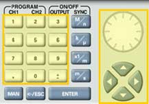
3. After selecting the attribute for modification, modify the displayed value using the dial or the cursor keys, or by entering the value using the numeric keypad. Press ENTER to save the modified parameter value.
4. To configure the pulse setup, press the Config menu button.
5. The pulse configuration menu is displayed as shown below:
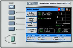
Select and modify configuration parameters as necessary:
- Pulse Parameters. Choose to specify pulse width, leading edge width, and trailing edge width as a time interval or as a percentage of the pulse period.
- Pulse Mode. Choose to generate single, delayed, or double pulses.
- Polarity. Choose from normal polarity, inverted polarity (pulse is inverted about its zero-amplitude baseline) and complemented polarity (pulse is inverted about its mid-amplitude axis).
- Transition Type. Select one of the following pulse transition types:
• Fast. The transition from low level to high level (and from high level to low level) is nearly instantaneous, occurring within 1 nanosecond.
• Linear. For linear, interval-configurable leading edge and trailing edge transitions.
• Symmetrical. For linear, interval-configurable leading edge and trailing edge transitions. When you configure the leading edge interval, the trailing edge interval is automatically configured with the same value.
- Level Control. Program pulses as high/low, amplitude/offset, positive, or negative.
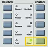
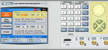
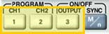
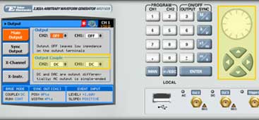
6. Press the Output button in the control menu to configure the output settings.
7. Define the channels in the Output section as being ON or OFF, modifying the settings using the dial or the cursor keys.
TIP
You can quickly modify the output settings by selecting CH1 or CH2 on the keypad, and toggling the OUTPUT key to turn the channel on or off.
8. Select the output path of the channels in the Output Couple section, modifying the settings using the dial or the cursor keys.
- DC (2Vp-p into 50Ω DC coupled)
- HV (High-Voltage 4Vp-p into 50Ω DC coupled)
- AC (-20 to +10 dBm into 50Ω AC coupled)
Press ENTER to save the output settings.
For More Information
To learn more about Tabor’s solutions or to schedule a demo, please contact your local Tabor representative or email your request to [email protected]