Frequency Hop Modulation is a method of transmitting radio signals by rapidly switching a carrier wave over a series of distinct frequency channels. Frequency hop modulation causes the output waveform to “hop” from frequency to frequency in a table-defined sequence.
The Tabor family of Arbitrary Waveform Generators (AWGs) allows you to easily generate a frequency hop modulation. This document will quickly guide you through the definition process.
NOTE
You can also generate an Amplitude Hop Modulation by following steps similar to those described in this document.
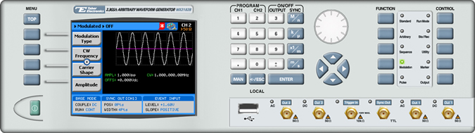
The front panel of the AWG is depicted below.
- To generate a Frequency Hop Modulation using the front panel:
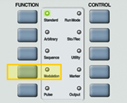
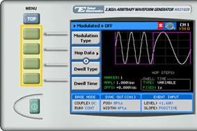
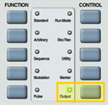
1. Press the Modulation button in the function menu.
2. Press the Modulation Type menu button. A list of modulation types appears on the screen. By default, the modulation type is set to “OFF”.
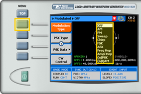
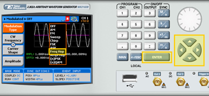
3. Select the Freq Hop modulation type from the list box using the arrow keys, and press ENTER.
4. Following your selection, you will be able to configure the characteristics of the modulation with the modulation-type specific menu buttons that appear on the left-hand side of the panel.
TIP
Whenever the arrows icon is displayed there are more attribute menu buttons to be shown below. Simply scroll down using the dial or cursor key.
5. Choose the menu buttons on the left-hand side of the screen to modify any of the following attributes:
- Hop Data. Create a table of frequency hops as explained in step 6.
- Dwell Type. Select a fixed or variable dwell time.
- Dwell Time. The time interval during which the frequency remains stable before hopping to the next frequency.
- Marker. “Marks” an index point in the table at which the Sync Output generates a pulse.
- Carrier Shape. The shape of the carrier wave – for example, a sine wave, triangle, or square.
- Amplitude. The amplitude of the carrier wave (in Volts peak-to-peak).
- Offset. The amplitude (in VDC) offset with reference to zero-level amplitude.
6. Press the Hop Data menu button to program a sequence of frequency hops, as shown below.
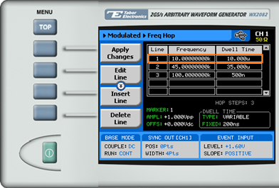
Each row in the table includes the following parameters:
- Line.The index number of the hop.
- Frequency.The frequency of the hop.
- Dwell Time. The dwell time of the hop. The dwell times in the table will be used only if a variable dwell time is specified in the Dwell Type attribute.
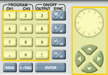
7. When selecting a numeric attribute for modification, modify the displayed value using the dial or the cursor keys, or by entering the value using the numeric keypad. Press ENTER to save the modified parameter value.
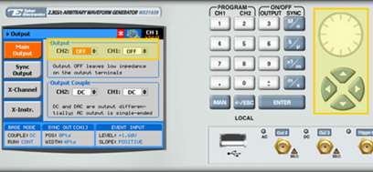
8. Press the Output button in the control menu to configure the output settings.
9. Define the channels in the Output section as being ON or OFF, modifying the settings using the dial or the cursor keys.
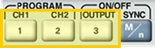
TIP
You can quickly modify the output settings by selecting CH1 or CH2 on the keypad, and toggling the OUTPUT key to turn the channel on or off.
10. Select the output path of the channels in the Output Couple section, modifying the settings using the dial or the cursor keys.
- DC (2Vp-p into 50Ω DC coupled)
- HV (High-Voltage 4Vp-p into 50Ω DC coupled)
- AC (-20 to +10 dBm into 50Ω AC coupled)
Press ENTER to save the output settings.
For More Information
To learn more about Tabor’s solutions or to schedule a demo, please contact your local Tabor representative or email your request to [email protected]