Pseudo Random Bit Sequences (PRBS) are commonly used for bit error rate measurements. PRBS sequences are extremely beneficial for applications in which sequences are generated by a transmitter and are then evaluated for errors as they arrive at the receiver.
You can use the Tabor Electronics Arbitrary Waveform Generator (AWG) front panel to create PBRS patterns. The AWG supports the following PBRS types: PRBS 27, PRBS 29, PRBS 211, PRBS 215, PRBS 223, PRBS 231, as well as an additional user-defined PRBS type.
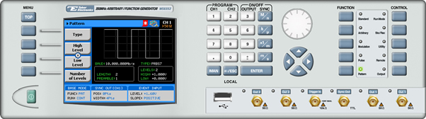
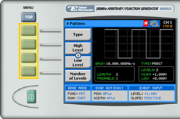
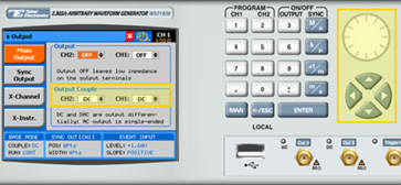
Once a PBRS type is chosen, the AWG allows you to configure additional characteristics, including high-level and low-level values, the number of levels, the baud rate, pattern length, and preamble length. The front panel of the AWG is depicted below.
- To generate PRBS signals using the front panel:
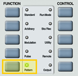
1. Press the Patternbutton in the function menu.
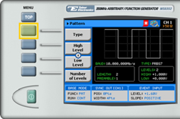
2. Press the Type menu button.
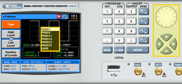
3. Select one of the pattern types from the list box using the dial or the cursor keys, and press ENTER.
4. Now that you have selected a pattern type, you can press the menu buttons on the left-hand side of the panel to select additional PRBS attributes for modification:
- High Level. The high-level voltage value.
- Low Level. The low-level voltage value.
- Number of levels. From 2 to 5 levels are supported.
- Baud. The baud rate of the sequence (in Mbps).
- Length. The pulse length of the PRBS patter (in bits).
- Preamble. The length of the synchronization interval (in bits).
TIP
Whenever the arrows icon is displayed there are more attribute menu buttons to be shown below. Simply scroll down using the dial or cursor key.
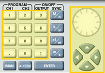
5. After selecting the attribute for modification, modify the displayed value using the dial or the cursor keys, or by entering the value using the numeric keypad. Press ENTER to save the modified parameter value.
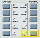
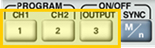
6. Press the Output button in the control menu to configure the output settings.
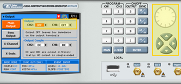
7. Define the channels in the Output section as being ON or OFF, modifying the settings using the dial or the cursor keys.
TIP
You can quickly modify the output settings by selecting CH1 or CH2 on the keypad, and toggling the OUTPUT key to turn the channel on or off.
8. Select the output path of the channels in the Output Couple section, modifying the settings using the dial or the cursor keys.
- DC (2Vp-p into 50Ω DC coupled)
- HV (High-Voltage 4Vp-p into 50Ω DC coupled)
- AC (-20 to +10 dBm into 50Ω AC coupled)
Press ENTER to save the output settings.
For More Information
To learn more about Tabor’s solutions or to schedule a demo, please contact your local Tabor representative or email your request to [email protected]