The WX series of Arbitrary Waveform Generators (AWGs) enables independent and synchronized modes of operation in its multi-channel units. In addition, all units support operation with an external clock and an external clock reference when required.
- External Sample Clock (SCLK) – an external clock source is connected to the ‘SCLK IN’ SMA connector on the rear panel. It accepts signals within the frequency range of 2 GHz to 4.6 GHz (double the internal SCLK) in all single and dual channel units and 100 MHz to 2.3 GHz in the 4-Channel units.
- External Clock Reference – an external reference clock is connected to the BNC connector on the rear panel. It accepts signals with the frequencies: 10, 20, 50 and 100 MHz.
This document will quickly guide you through the definition process.
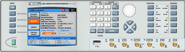
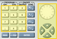
The front panel of the AWG is depicted below.
- To define the clock using the front panel:
1. Press the Utility button in the function menu.
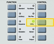
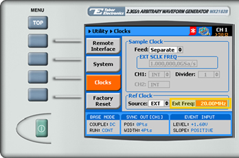
2. Press the Clocks menu button to select separate or common feed, EXT or INT SCLK, and EXT or INT SCLK reference.
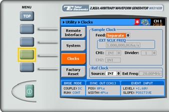
3. Choose the sample clock Feed.
- In Separate mode, each output channel can be programmed to a different run mode option.
- In Common mode, both channels are synchronized and are fed from the same SCLK. Therefore, selecting a specific run mode option for one channel automatically selects the identical mode in the other channel.
NOTE
EXT SCLK is available only in Arbitrary or Sequence mode. When EXT SCLK is selected all channels are synchronized and are fed from the same EXT SCLK.
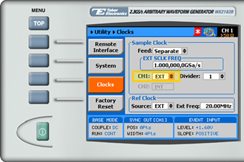
4. Verify that the unit is in Arbitrary or Sequence mode. Select the EXT option in the CH1 field. The EXT SCLK FREQ and Divider field are activated.
5. When selecting a numeric attribute for modification, modify the displayed value using the dial or the cursor keys, or by entering the value using the numeric keypad. Press ENTER to save the modified parameter value.
6. Modify the Divider field if a different frequency is to be generated from the second channel. The divider field accepts values corresponding to the expression 2n, in the range from 1 to 256. This value is used to external sample clock frequency before it is applied to the internal circuits.
7. Navigate to the Ref Clock Source field, and select EXT. The Ext Freq field is activated.
Modify the Ext Freq field to match the external reference source frequency.
For More Information
To learn more about Tabor’s solutions or to schedule a demo, please contact your local Tabor representative or email your request to [email protected]