Sequenced waveforms are constructed from two or more arbitrary waveform segments. An advanced sequence waveform is constructed from two or more sequenced waveforms – a “sequence of sequences”.
The Tabor family of Arbitrary Waveform Generators (AWGs) allows you to program individual sequences, and then combine them using the advanced sequencing function. This document will quickly guide you through the definition process.
NOTE
Waveform sequences must be generated before constructing an advanced sequence. See How to Simply Generate a Sequence for further information.
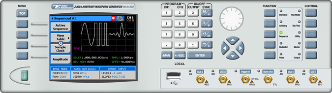
The front panel of the AWG is depicted below.
- To generate an advanced sequence using the front panel:
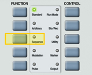
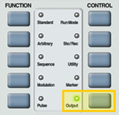
1. Press the Sequence button in the function menu.
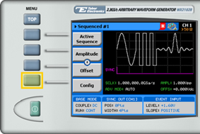
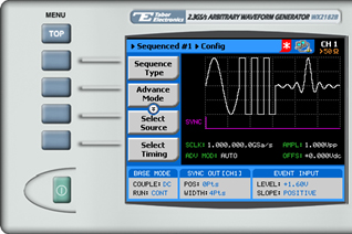
2. Press the Config menu button.
TIP
Whenever the arrows icon is displayed there are more attribute menu buttons to be shown below. Simply scroll down using the dial or cursor key.
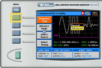
3. Press the Sequence Type menu button. Select Advanced from the list box using the arrow keys, and press ENTER.
4. Press ESC to exit the Config menu.
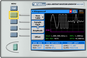
5. Choose the menu buttons on the left-hand side of the screen to modify any of the following attributes:
- View Table. A table used to program the sequence in which the sequenced waveforms will be generated, as explained in step 6.
- Sample Clock. Specifies the sample clock frequency, measured in samples/second
- Amplitude. The amplitude of the sequenced waveform (in Volts peak-to-peak).
- Offset. The amplitude offset (in Volts peak-to-peak) with reference to zero-level amplitude.
- Config. Contains additional configuration options.
6. Press the View Table menu button.
7. Use the view table (shown below) to program a sequence of sequenced waveforms.
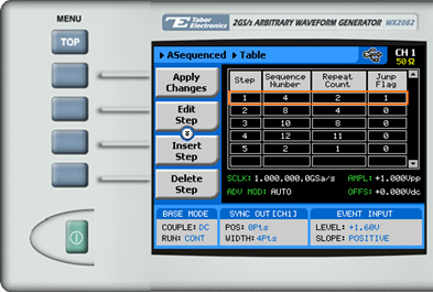
Each row in the table includes the following parameters:
- Step. The index number of the row.
- Sequence Number. The sequence number of the arbitrary waveform to be replayed.
- Repeat Count. The number of times the sequence is to be replayed.
- Jump Flag. Specifies how to proceed at the end of a sequence replay: Enter “0” continue to the next sequence automatically, enter “1” to wait for an event before proceeding.
NOTE
The advanced sequence table must have a minimum of 3 steps in order to enable advanced sequence generation.
8. Press ESC to exit the View Table menu.
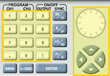
9. When selecting a numeric attribute for modification, modify the displayed value using the dial or the cursor keys, or by entering the value using the numeric keypad. Press ENTER to save the modified parameter value.
10. Press the Config menu button.
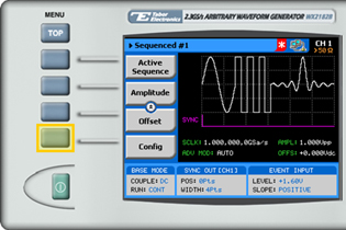
The sequence configuration menu is displayed as shown below:
11. Select and modify configuration parameters as necessary:
- Sequence Type. Specifies whether the sequence is Normal or Advanced. For information on normal sequences, see How to Simply Generate a Normal Sequence.
- Advance Mode. Select the method for advancing to the next step in the table:
• Auto. Automatic advancement to the next step (as long as a Jump Bit flag has not been set). At the end of the sequence, the sequence is repeated from the beginning
• Once. Automatic advancement to the next step (as long as a Jump Bit flag has not been set). At the end of the sequence, the sequence is not repeated. This mode supports a repeat loop and counter that can be used to repeatedly run a single sequence.
• Stepped. In this mode, a Jump Bit flag is appended to each step in the sequence. Therefore, advancement to the next step occurs only following assertion of a jump event signal.
- Jump Event. Specifies the source that will provide jump events, signaling the start of a new segment. This button appears when Auto or Step are selected in the Config >> Advance Mode menu.
• Bus. The jump event is controlled by remote PC commands.
• Event. An external source dynamically asserts control via the AWG’s rear-panel, 9-pin control connector.
- Sync Lock. Specifies the step number in the sequence that generates the Sync Output pulse.
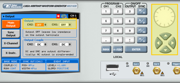
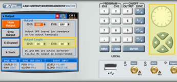
12. Press the Output button in the control menu to configure the output settings.
13. Define the channels in the Output section as being ON or OFF, modifying the settings using the dial or the cursor keys.
TIP
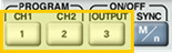
You can quickly modify the output settings by selecting CH1 or CH2 on the keypad, and toggling the OUTPUT key to turn the channel on or off.
14. Select the output path of the channels in the Output Couple section, modifying the settings using the dial or the cursor keys.
- DC (2Vp-p into 50Ω DC coupled)
- HV (High-Voltage 4Vp-p into 50&Omega DC coupled)
- AC (-20 to +10 dBm into 50Ω AC coupled)
Press ENTER to save the output settings.
For More Information
To learn more about Tabor’s solutions or to schedule a demo, please contact your local Tabor representative or email your request to [email protected]