In the previous tutorial, we have shown how to communicate with Tabor AWG using SCPI commands. Another way of using the Test & Measurement Tool, is by creating a device object using the Tabor IVI driver. This way, one can communicate with the Tabor AWG, using pre-defined functions. In this tutorial, we will give a quick start guide on how you can communicate with the Tabor AWG using the IVI driver.
In order to control instruments using MATLAB, the instrument control toolbox is required. Please note that the Instrument Control Toolbox is an additional application that needs to be added. For more information you can visit the Mathworks website.
For this tutorial, we will use MATLAB version R2014a 32bit and a USB interface. We will demonstrate it using Tabor WX2184C and the latest WX218xx IVI driver. There are differences with operating WW AWGs which use the WW257xx IVI driver but the basics are the same. To ensure you successfully established all the necessary settings for remote control over the Tabor instrument using LAN/USB/GPIB, please go over the connectivity tutorials on the Tabor’s website.
- To connect and control the Tabor’s Instrument using the Test & Measurement Tool
1. First you may need to choose a MATLAB compiler. There is a need to check that MATLAB uses Microsoft visual C++ compiler or another compiler that can read C (as the IVI driver is written in C language).
Please enter the following command:
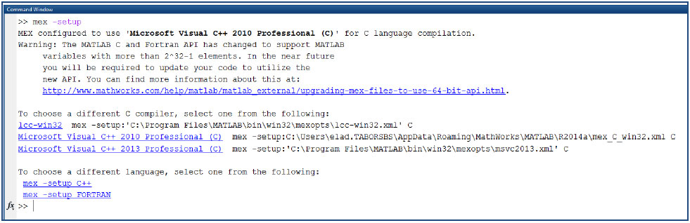
It will start a routine that should allow you to view/choose between all avialable compilers. In case you don’t have any C/C++ compiler as an option, please use the following links to finish this routine:
a. https://www.mathworks.com/matlabcentral/answers/101105-how-do-i-install-microsoft-windows-sdk-7-1
b. http://www.mathworks.com/support/compilers/R2016b/
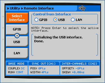
2. Set the USB/LAN/GPIB as the remote interface, using the Tabor’s front panel buttons. To do so, go to: “Utility”->”Remote Interface”->”Select Interface”->”Control from Interface”. Press Enter to select the active Interface you need. Wait for the answer “Done”. We chose to demonstrate using USB.
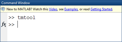
3. Once the MATLAB is up and running, type “tmtool” on the command window to open the Test & Measurement Tool.
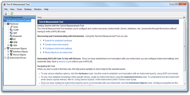
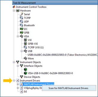
A new Test & Measurement Tool dialog box opens up:
4. Click on “Instrument Drivers” and then right click on MATLAB Instrument drivers and select “Scan for MATLAB Intstrument Drivers” :
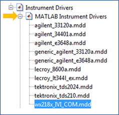
5. Click on “MATLAB Instrument Drivers” to see the list of supported IVI drivers:
NOTE
If the Tabor ‘wx218x_IVI_COM.mdd’ file isn’t there, please refer to the instructions in “How to Connect to Tabor Using Instrument Control Toolbox”” tutorial, regarding how to copy & paste this ‘*.mdd’ file to MATLAB’s ‘Drivers’ folder.
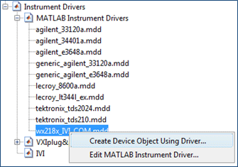
6. Right click on “wx218x_IVI_COM.mdd”. Choose “Create Device Object Using Driver…”
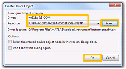
7. A new window pops out. Click on ‘Scan’. Make sure the address and driver are the correct ones for this specific AWG. Click on ‘OK’ to create a device object:
A new device object should appear:
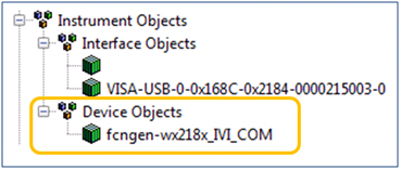
8. Click on the ‘fcngen-wx218x_IVI_COM’ and a new dialog box will pop up:
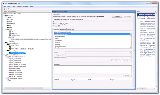
On the Device Object dialog box you will see ‘Functions’, ‘Properties’ and ‘Session Log’.
- Functions - Allows you to communicate with the device using its driver functions.
- Properties – Allows you to set parameters and modes regarding the device under control.
- Session Log – Allows you to save the last session as MATLAB script.
9. Here is a short basic example, to set a 50MHz 2Vp-p square waveform in standard mode, just to get a feel of how to communicate using the IVI driver.
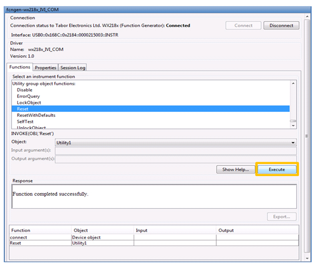
a. Press on the ‘Connect’ button.
b. After successfully connecting to Tabor, execute the ‘Reset’ function under ‘Utility group object functions’ as shown below. A new action line should appear.
c. Execute the ‘SetActiveChannel’ function under ‘Device object functions’. As input type: ‘channel1’ and click on ‘Execute’.

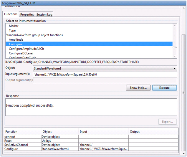
d. Execute the ‘configure’ function under ‘StandardWaveform group object functions’. As inputs type:
‘channel1’, ’WX218xWaveformSquare’, 2, 0, 50e6, 0. Then click on ‘Execute’ to set the waveform parameters.
e. Finally execute the ‘Enable’ function under ‘Output group object functions’. As input, type: ‘channel1’, 1 to turn CH1 on (0 to turn CH1 off). After doing so, press on the ‘Disconnect’ button.
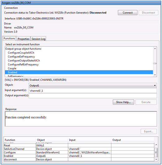
As can be seen above, each time you press the ‘Execute’ button, the function you executed is also saved as an action line that can be used later on as part of a MATLAB script for automation purposes.
Each time a function is successfully executed, you can go to the ‘Session Log’ and see its syntax. You could also copy and paste it to a different MATLAB script . This is a great helping tool for those who are new to the IVI driver functions used with Tabor AWGs.
10. As can be seen on scope, a 50MHz 2Vp-p square waveform was created:
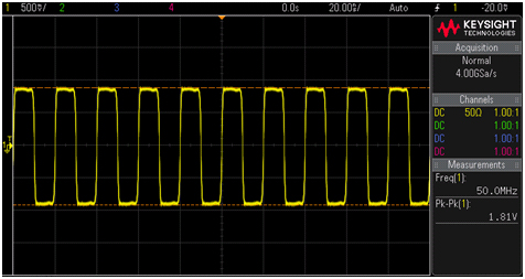
The outputted 50MHz 2Vp-p square waveform.
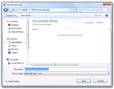
11. In order to save this process as a MATLAB code, go to ‘Session log’ where you will see that all the actions you have made were automatically translated into MATLAB code. Press the ‘Save Session’ button to save as MATLAB script.
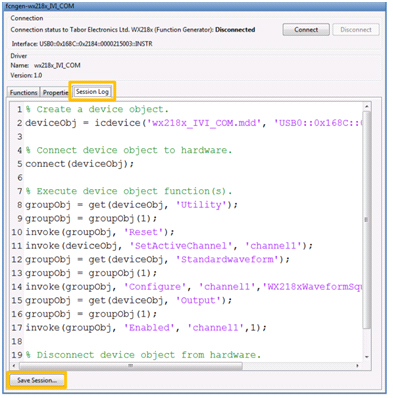
And save your session as MATLAB script:
11. For more information regarding the IVI driver functions:
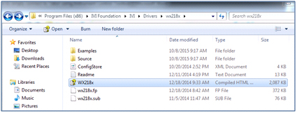
a. Go to: C:\Program Files (x86)\IVI Foundation\IVI\Drivers\wx218x
i. Open the “WX218x” file:
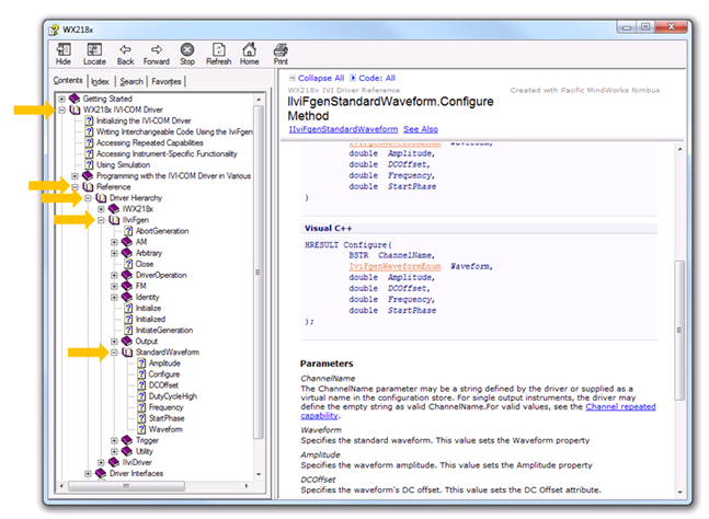
ii. Follow the path as shown below:
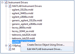
b. In MATLAB’s Test & Measurement Tool, you can also have a look at the functions syntax by:
i. right clicking on “wx218x_IVI_COM.mdd”and choosing “Edit MATLAB Instrument Driver”.
ii. To see the functions syntax extend:
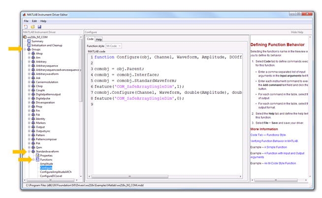
‘Groups’->chose group of interest->’Functions’->chose function of interest
In the next four tutorials of the series “How to Control Tabor AWGs with MATLAB”, we will show four practical MATLAB coding examples.
For More Information
For more of Tabor’s solutions or to schedule a demo, please contact your local Tabor representative or email your request to info@tabor.co.il