Phase-Shift Keying (PSK) is a technique used to transmit data by modifying the phase of a sinusoid carrier wave. Tabor Arbitrary Waveform Generators (AWGs) supports PSK modulation according to the following variations: PSK, BPSK, QPSK, OQPSK, pi/4DQPSK, 8PSK, 16PSK, as well as user-defined variations. This document will quickly guide you through the definition process as shown on a WW2572A.
NOTE
You can also generate Quadrature Amplitude Modulation (QAM) by following steps similar to those described in this document. The (n)PSK and (n)QAM modulations are available in the WW2572A, WW5064/1074/2074, WS8102 and PM8572A models.
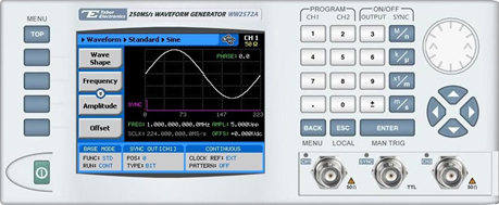
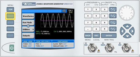
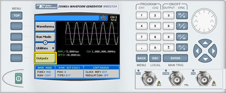
The front panel of the AWG is depicted below.
- To generate a PSK Modulation using the front panel:
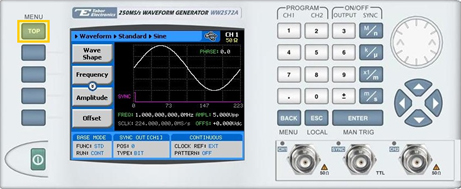
1. Press the TOP menu button.
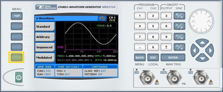
2. Press the Waveform button.
3. Press the Modulated button.
4. Press the Modulation Type menu button. A list of modulation types appears on the screen. By default, the modulation type is set to “OFF”.
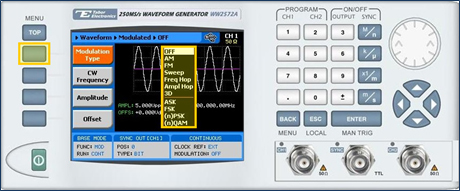
5. Select the (n)PSK modulation type from the list box using the arrow keys, and press ENTER.
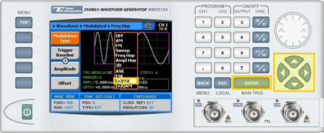
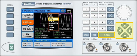
6. Press the PSK Type menu button. A list of PSK varieties appears on the screen.
- PSK
- BPSK
- QPSK
- OQPSK
- pi/4DQPSK
- 8PSK
- 16PSK
- USER (user-defined)
7. Select the required PSK modulation from the list box using the arrow keys, and press ENTER.
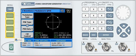
8. Following your selection, you will be able to configure the characteristics of the modulation with the modulation-type specific menu buttons that appear on the left-hand side of the panel.
TIP
Whenever the arrows icon is displayed there are more attribute menu buttons to be shown below. Simply scroll down using the dial or cursor key.
9. Choose the menu buttons on the left-hand side of the screen to modify any of the following attributes:
- PSK Data. A table used to program a sequence of phase changes, as shown in step 10.
- CW Control. Used to turn the carrier waveform CW OFF or CW ON.
- CW Frequency. The frequency of the sinusoid carrier waveform.
- Symbol Rate. The rate at which the symbols step through. The rate can be programmed within the range of 1 S/s to 1 MS/s (when the length of the symbol is a single bit).
- Marker. Defines an index point in the PSK sequence at which the Sync Output generates a marker pulse.
- Amplitude. The amplitude of the carrier wave (in Volts peak-to-peak).
- Offset. The amplitude (in VDC) offset with reference to zero-level amplitude.
10. Press the PSK Data menu button to program a sequence of phase changes, as shown below.
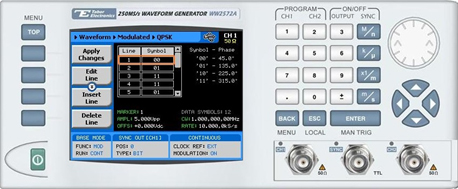
Each row in the table includes the following parameters:
- Line. The index number of the row.
- Symbol. The PSK data symbol. Each symbol defines a specified phase shift.
The following operations can be performed on the table:
- Edit Line. To edit an existing row.
- Insert Line. To add a new row to the table.
- Delete Line. To delete an existing row from the table.
- Load DEMO Table. To restore the factory-set demo values to the table.
- Delete Table. To delete the entire table.
- Apply Changes. Applies all the changes made to the table.
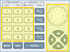
11. When selecting a numeric attribute for modification, modify the displayed value either by using the dial or the cursor keys, or by entering the value using the numeric keypad. Press ENTER to save the modified parameter value.
12. Press the TOP menu button to return to the main menu.
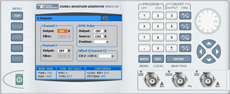
13. Press the Outputs button to configure the output settings.
14. Define the channels in the Outputs section as beingON or OFF, modifying the settings using the dial or the cursor keys:
- To scroll between the fields, use the cursor keys.
- To edit a field, select the field, and press ENTER. Use the keypad to enter the chosen value.
- To toggle between ON and OFF, select the field and press ENTER. Use the cursor keys to choose the selected option.
- Press ENTER again to exit the edit mode, and save the value.
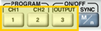
TIP
You can quickly modify the output settings by selecting CH1 or CH2 on the keypad, and toggling the OUTPUT key to turn the channel on or off.
For More Information
To learn more about Tabor’s solutions or to schedule a demo, please contact your local Tabor representative or email your request to info@tabor.co.il.